



Product Specifications
| Parameter | Specification |
| Characteristic impedance | 90 Ω |
| Cable outer diameter | 4.6 mm |
| USB interface | USB 2.0 |
| PCM part number | PCM-ZC-0229 |
| Shield termination | Shell to shell |
| Insulation resistance | 100 MΩ minimum |
| Dielectric withstand voltage | 500 V RMS minimum |
| P2 insulation case | Hirose GT32-4DS-1.5C |
| Axial pull strength | 110 N minimum per drawing |
| Operating temperature | −40 °C to +105 °C per drawing |
| Insertion and extraction durability | 25 cycles minimum per drawing |
| Connector P2 | Hirose GT32 A Key with four positions |
| P2 housing | Original Hirose GT32-4DS-HU(A), brown |
| Cable length | 600 ± 20 mm between drawing reference points |
| Conductor construction | One 26 AWG data pair and two 24 AWG conductors |
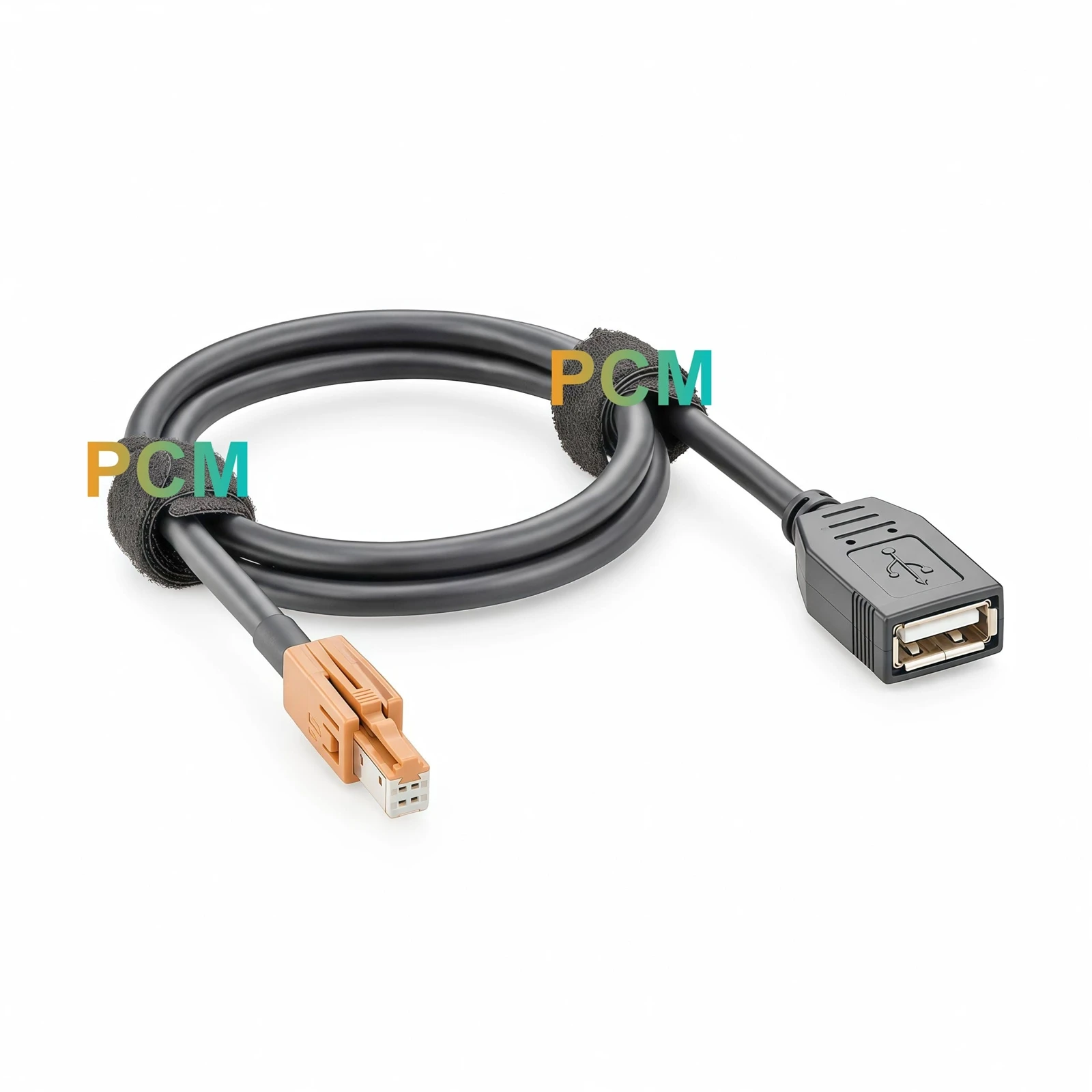
| Connector P1 | USB Type A female receptacle with molded housing |
From a Keyed Module Connection to an Accessible USB Port

USB Type A Female Receptacle for Peripheral Access
The molded USB 2.0 Type A female receptacle brings the connection point out from behind an infotainment module or fixture cover. Technicians can plug in a compatible peripheral or a Type A test lead without reaching the Hirose GT32 latch each time. The molded body gives operators a place to grip the receptacle during insertion and removal. For a fixed test station, a fixture holder can support the receptacle and keep it in a consistent position. Leave enough room in front of the holder for the mating plug and enough space behind it for the cable to exit without a tight bend.
Original Hirose A Key Housing and Latch
At the module end, the original brown Hirose GT32-4DS-HU(A) housing defines the A Key mating profile, and the latch retains the connector once fully seated. The Hirose GT32-4DS-1.5C insulation case positions the four contacts. Listing both part numbers in the cable specification gives purchasing teams a precise reference when comparing quotations or reviewing a sample. For installation, check the equipment connector part number against the Hirose mating profile and verify the module pin assignment separately. The A Key identifies the mechanical fit, while the equipment wiring determines USB compatibility.


600 mm Cable Run for Compact Layouts
The drawing specifies 600 ± 20 mm between the cable exit reference points. Use that dimension to check the actual route from the Hirose GT32 port to the intended USB access point, including any turns around brackets or covers. Allow additional space for both connector bodies, the inserted USB plug and access to the Hirose latch. The 4.6 mm cable diameter gives fixture designers a reference for selecting clips and routing guides. In a console prototype, these dimensions also let engineers check whether the receptacle remains reachable with the trim and nearby components in place.
Separate Paths for USB Ground and Shield Continuity
Inside the cable, a 26 AWG differential pair carries D− and D+, and two 24 AWG conductors carry VCC and GND. The drawing specifies a characteristic impedance of 90 Ω and shows the cable shield connecting the USB and Hirose GT32 shells. USB ground has its own conductor on pin 4. For a continuity fixture, the pin assignment gives technicians separate checks for each of the four conductors and the shell connection. It also gives engineers a reference for reviewing how the cable shield and USB ground connect to the module and the rest of the harness.
Where the USB Female End Fits
| Application | How PCM-ZC-0229 is used |
|---|---|
| Infotainment peripheral validation | Plug a supported USB flash drive or other peripheral into the Type A receptacle to check recognition and data access on a compatible head unit. |
| Console and media module prototyping | Position the USB connection where it can be reached while evaluating routing between a module and a proposed access point. |
| Production test fixtures | Keep the Hirose GT32 end seated on a compatible fixture interface while operators connect and remove Type A test leads at the accessible end. |
Product Drawing

Product FAQ
What plugs into the USB Type A female end ?
It accepts a USB Type A male plug from a compatible peripheral or test lead. Confirm that the equipment behind the Hirose GT32 interface supports the intended USB device.
Can I connect a USB flash drive through this cable ?
Yes, if the module at the Hirose end acts as a USB host and supports USB storage. The cable carries USB data and power between the module and the receptacle.
Does the USB receptacle have a panel mounting feature ?
The drawing shows a molded inline receptacle. If the port needs to stay fixed in a panel or fixture, plan for a separate holder that fits the receptacle body and leaves clearance for plug insertion.
Will it fit any four position Hirose GT32 interface ?
Check for a mating Hirose GT32 A Key connector and confirm the USB pin assignment. The brown GT32-4DS-HU(A) housing identifies the key used on this assembly.
Can PCM quote a different cable length ?
Send PCM the target length, measurement reference points and estimated quantity for review. The standard drawing specifies 600 ± 20 mm between the cable exit reference points.

Hot Tags: Hirose GT32 A Key To USB 2.0 Female Cable, China Hirose GT32 A Key To USB 2.0 Female Cable manufacturers, suppliers, factory


