Product Description
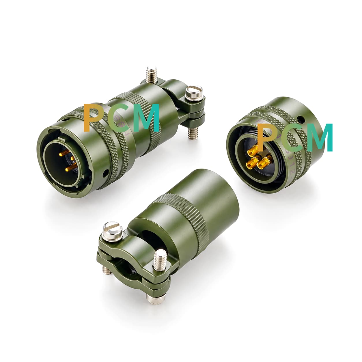
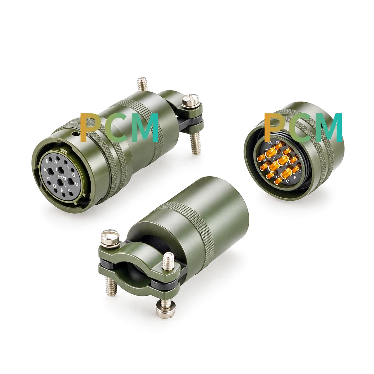
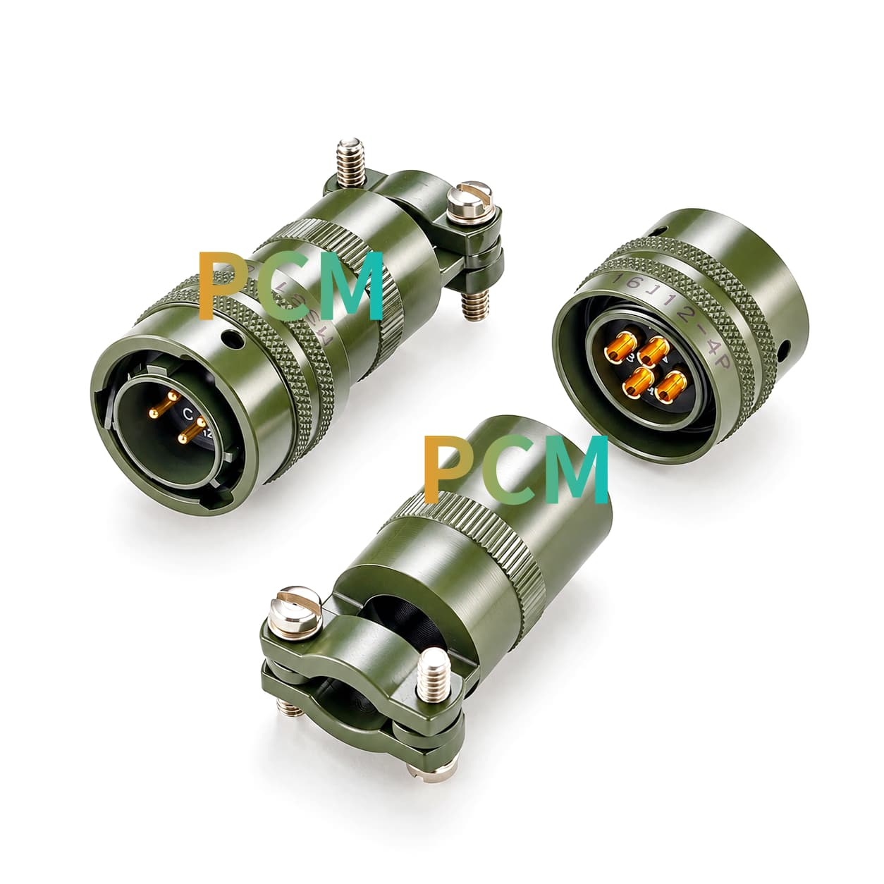
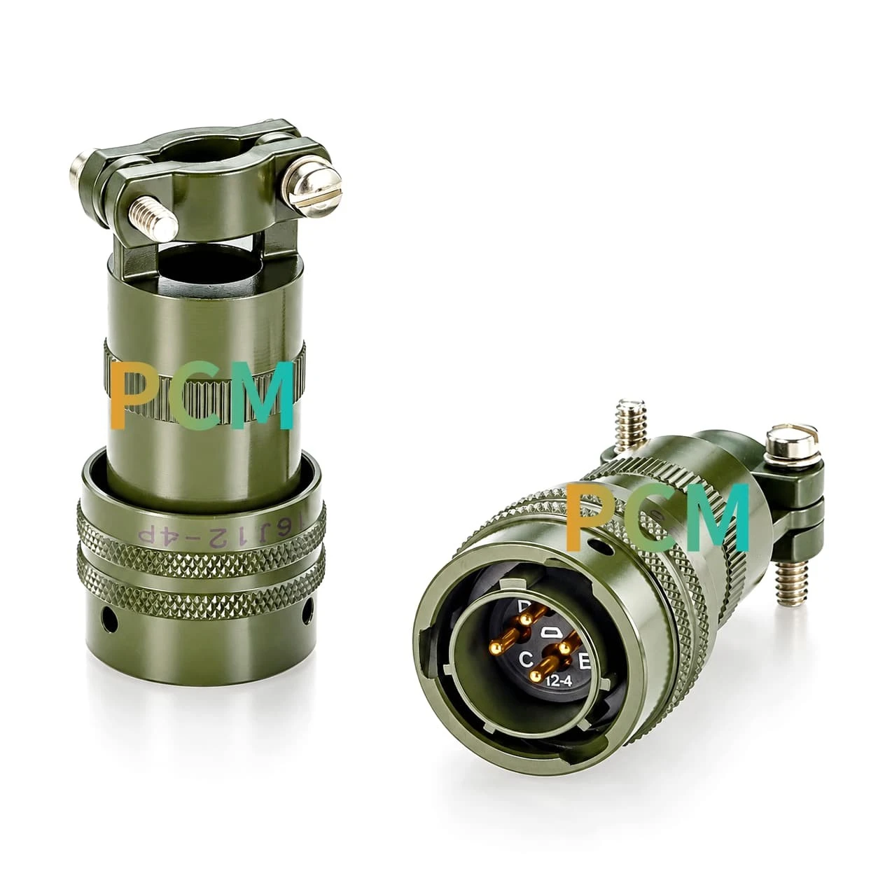
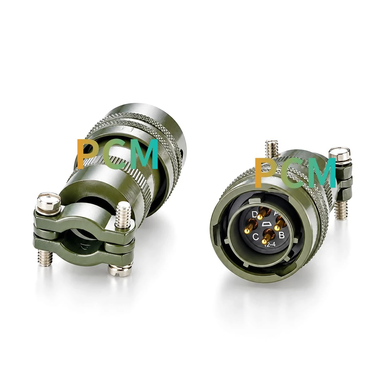
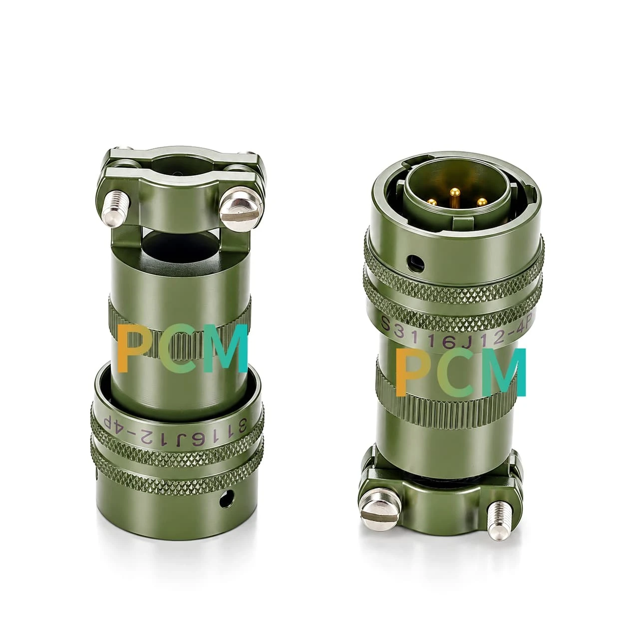
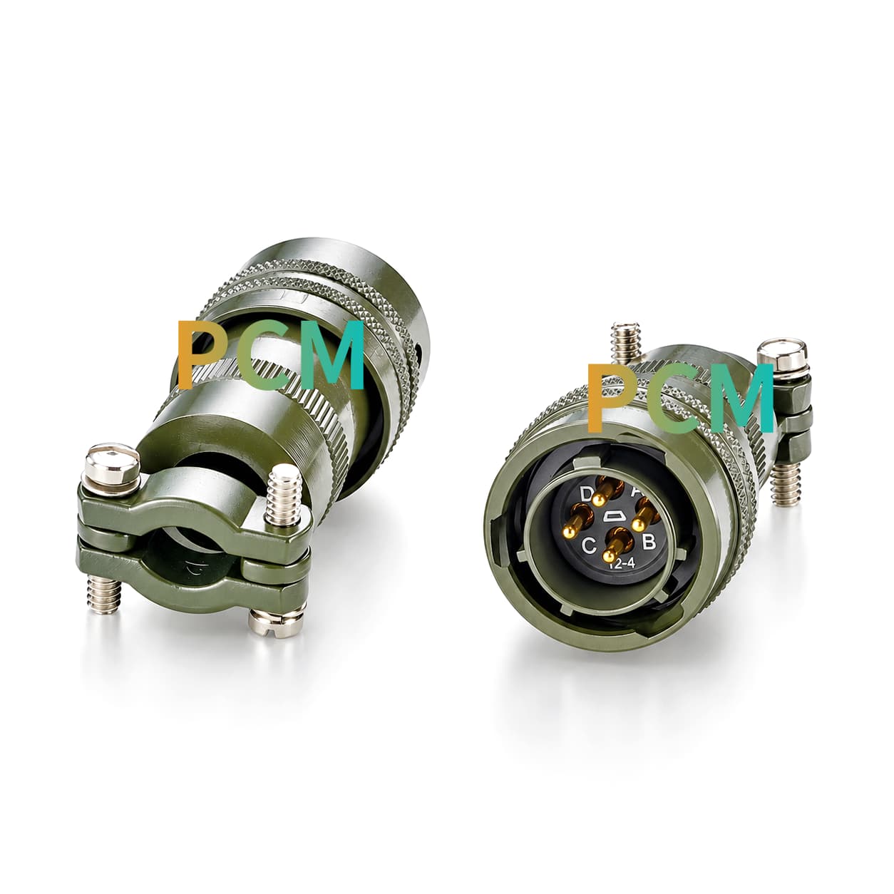
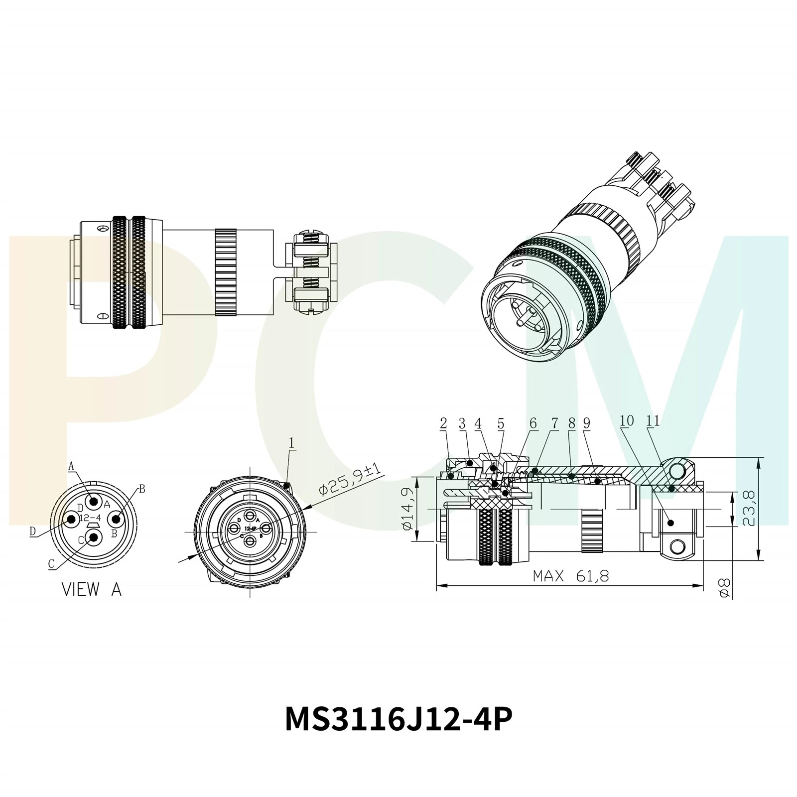
In the equipment diagnostic harness, four positions can be allocated for power supply, common circuit, trigger input, and status feedback. For example, a bench tester can supply power to the module under test, issue a test trigger signal, and read the module's status through an adapter cable. The rear end of the product uses a screw-type cable clamp, which can hold the matching cable sheath at the connector entrance during assembly.
The front operation area and rear cable fixation area are distributed along the axial direction, allowing engineers to separately plan the plug-and-play operation space, cable clamp assembly space, and rear bending line space. This layout is suitable for confirming the output direction in advance during the initial structural design of test fixtures or maintenance boxes.
Product Drawings
|
|
|
Product Features
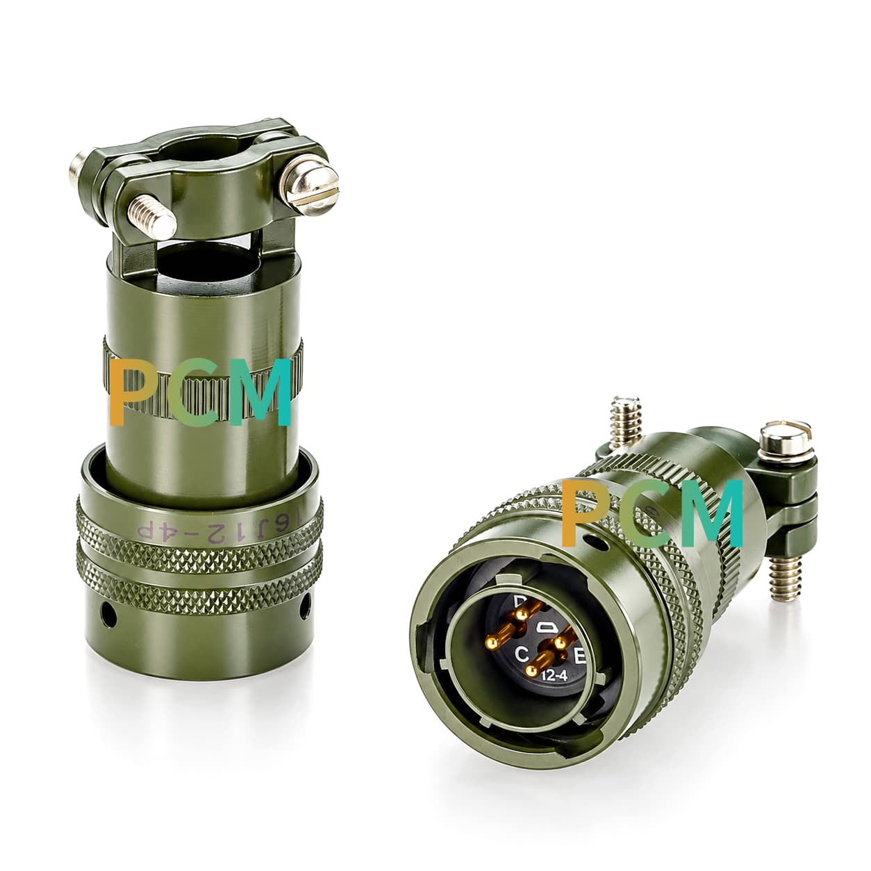
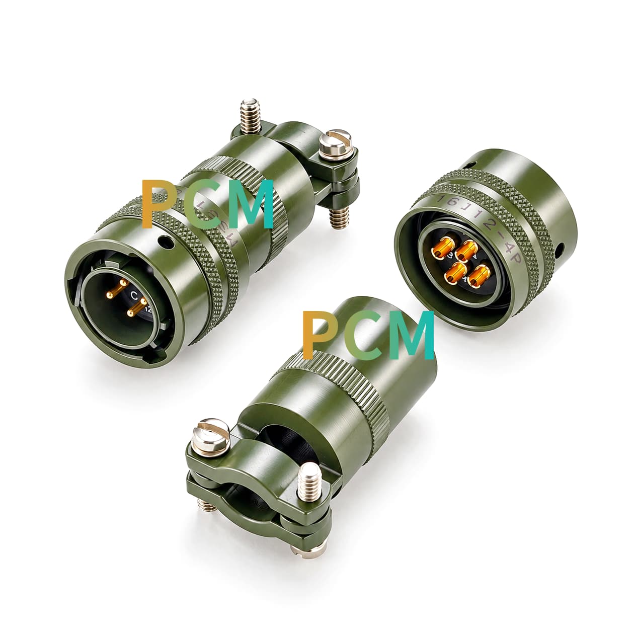
- Dual front knurling bands.
Two circumferential knurled bands provide a defined grip area at the front.
- Opposed rear clamp halves.
Two opposing clamp halves surround the cable exit and are tightened with screws.
- Axial cable path.
The cable exits along the connector centerline, allowing the exit to align with a straight routing zone.
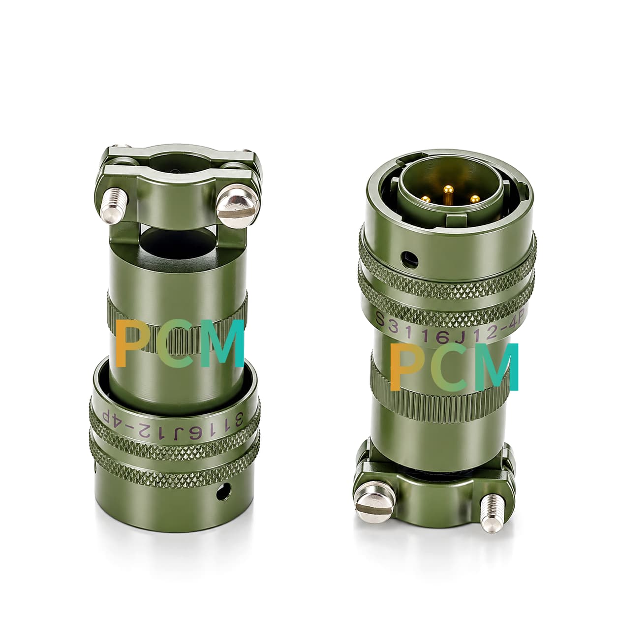
- Textured mid-body band.
The drawing shows a separate textured band between the front grip and rear clamp that can serve as a handling reference in assembly instructions.
Core Integration Benefits
- Consolidate external connections.
When the electrical requirements allow, bring a module's small set of circuits into one detachable interface to simplify fixture wiring.
- Define a clear boundary for continuity checks.
Managing the adapter lead as a separate assembly lets technicians check each circuit against the wiring table and narrow down the fault.
- Reuse the same bench across modules.
With a common bench-side interface and circuit assignment, operators can connect different devices by changing the device-side adapter lead.
- Stock spares as complete harnesses.
A dedicated assembly part number lets maintenance teams issue and replace the correct harness revision without rewiring at the station.
Product FAQ
Is 61.8 mm Enough Depth Inside an Enclosure ?
The 61.8 mm MAX callout is the maximum connector length shown in the drawing. For enclosure layout, also account for the mating component, connection and removal travel, access to the clamp, and the cable bend behind the connector.
Can the MS3116J12-4P mate with other MS3116 series connectors ?
Compatibility depends on the mating structure, insert arrangement, contact configuration, and product class. The MS3116 family designation alone does not guarantee compatibility. Full part numbers and mating drawings should be checked.
Can the MS3116J12-4P be supplied as a complete cable assembly ?
Yes. Premier Cable can develop customized harnesses according to project requirements, including connector integration, cable selection, specified lengths, and opposite-end connector configurations.
Can different cable lengths be customized for the MS3116J12-4P ?
Yes. Premier Cable can customize cable lengths according to equipment layouts and installation distances, with sample and bulk harness solutions available.
Get In Touch

Hot Tags: ms3116j12-4p connector, China ms3116j12-4p connector manufacturers, suppliers, factory