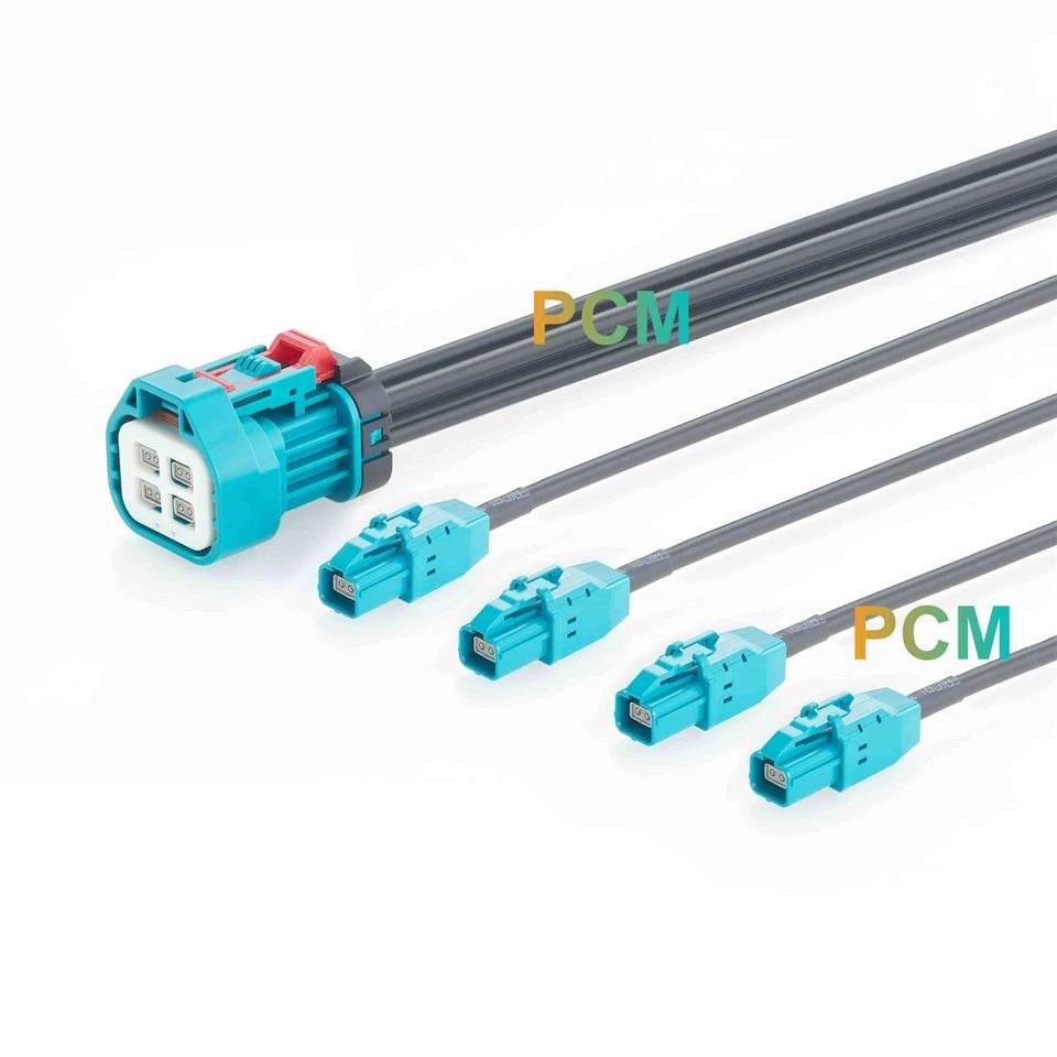
Product Specifications
| Parameter | Specification |
|---|---|
| Product Series | PCM-XY-0011 |
| Nominal Impedance | 100 Ω |
| Frequency Range | DC–5 GHz |
| Continuity Inspection | 100% tested |
| Cable Retention | 110 N minimum |
| Temperature Range | −40°C to +105°C |
| Protection Rating | P1: IP67 Waterproof |
| Dielectric Withstand | 500 VRMS minimum |
| Cable Model | ECT QFP12GD100-B-5G |
| Gender and Coding | Female to female, ECT Z Code |
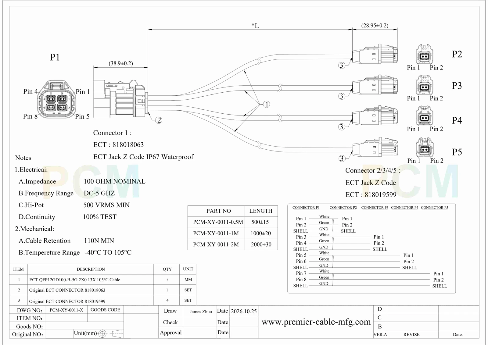
| Contact Arrangement | P1: 8 contacts in four pairs; P2–P5: 2 contacts each |
| Connector Combination | P1: ECT 818018063 × 1; P2–P5: ECT 818019599 × 4 |
Integrated Interface And Four Branch Structure
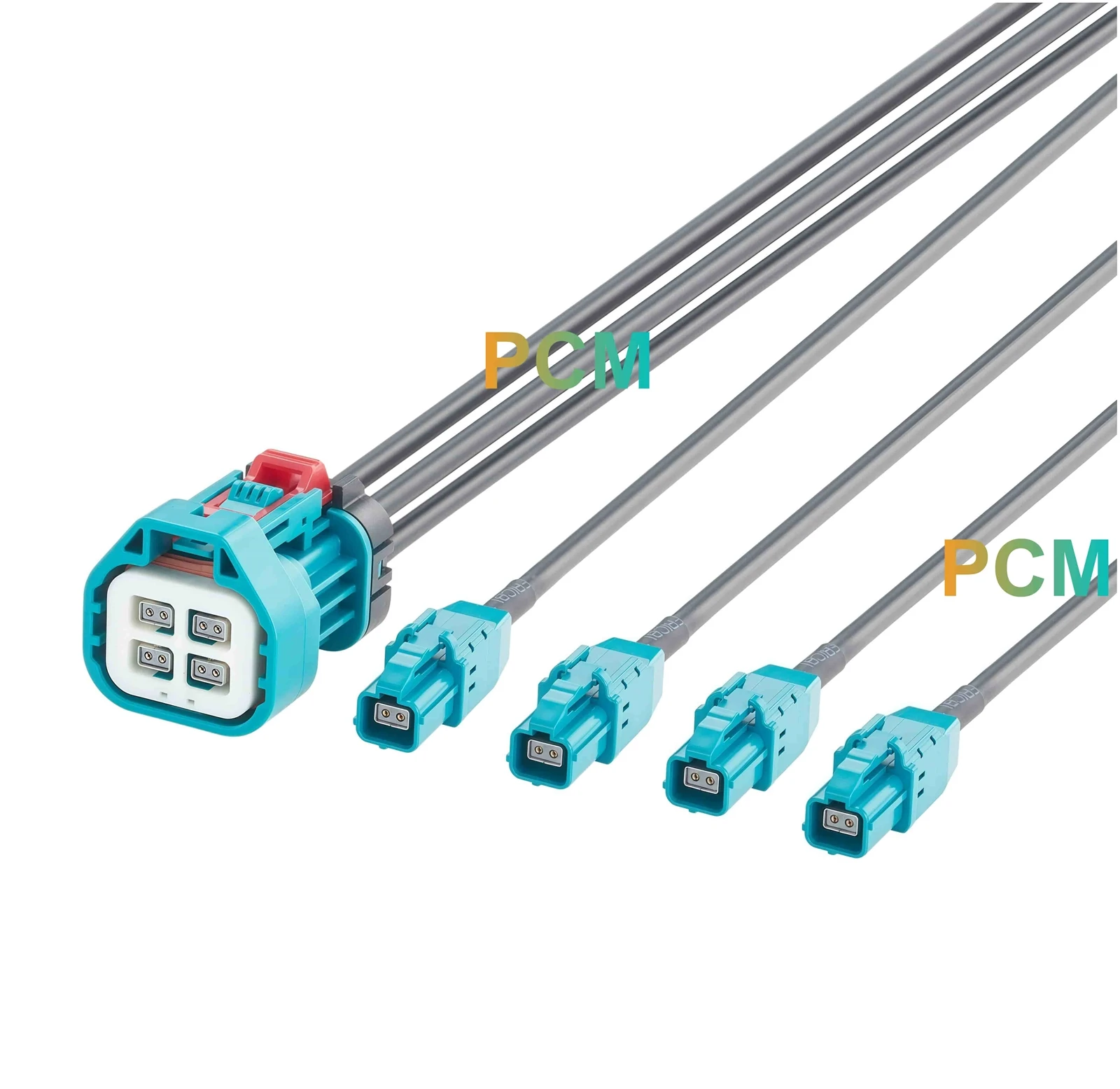
Four Contact Pairs Within One Housing
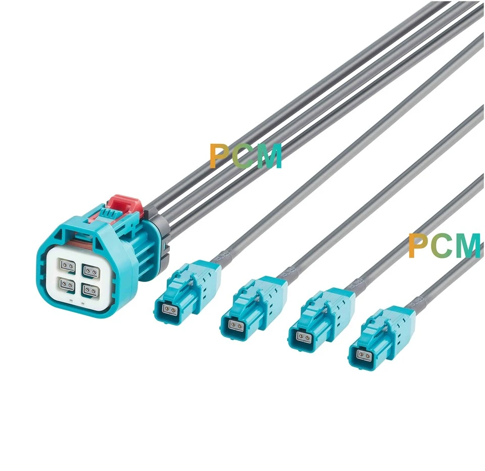
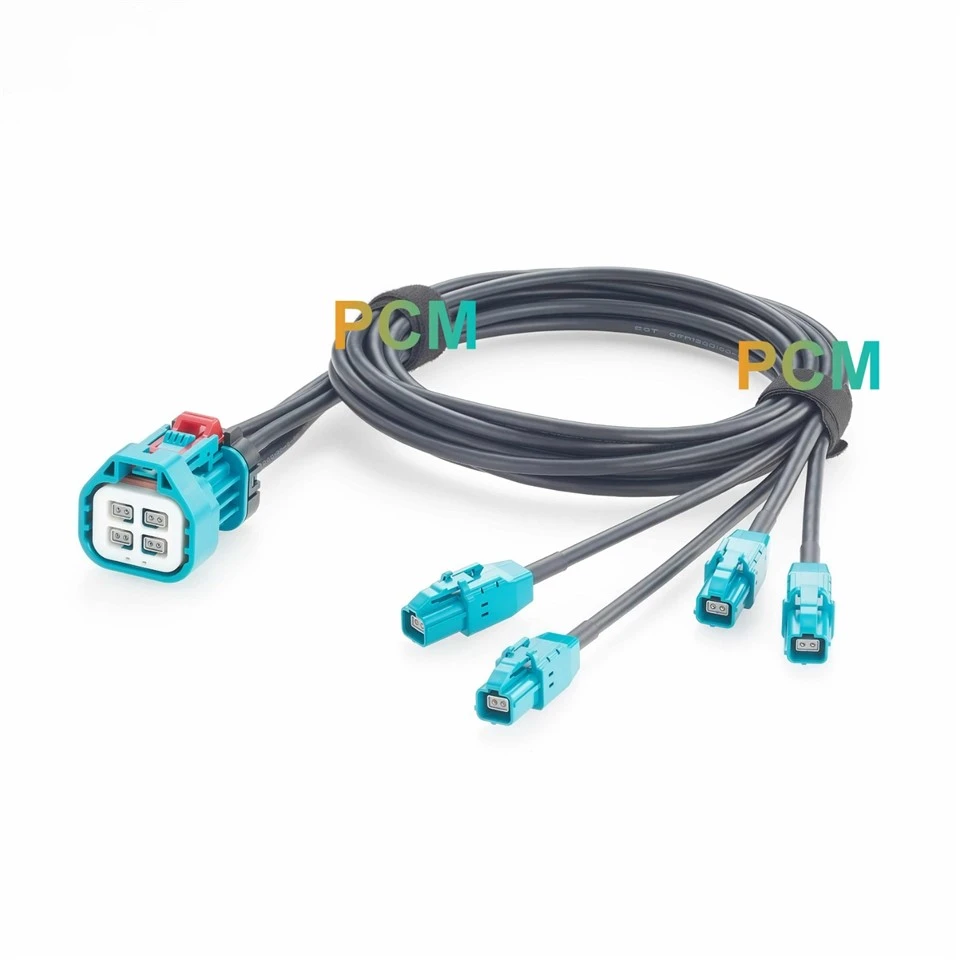
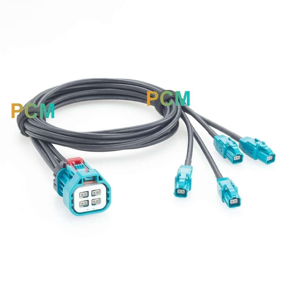
The P1 end combines four separate two contact interfaces in a compact two by two arrangement within one outer housing. A common mating opening brings the four channels together at a single equipment connection point. The photographed connector includes a white front insert, a surrounding turquoise housing and a red locking component, giving the integrated end a distinct mechanical structure.
Individual Branches With Defined Channel Mapping
Four separate cables extend from P1 to individually housed P2, P3, P4 and P5 jacks. Each branch carries its assigned contact pair: P1 pins 1–2 connect to P2, pins 3–4 to P3, pins 5–6 to P4, and pins 7–8 to P5. This arrangement preserves a direct channel to branch relationship, allowing the four cable paths to separate physically without introducing a shared parallel junction between channels.
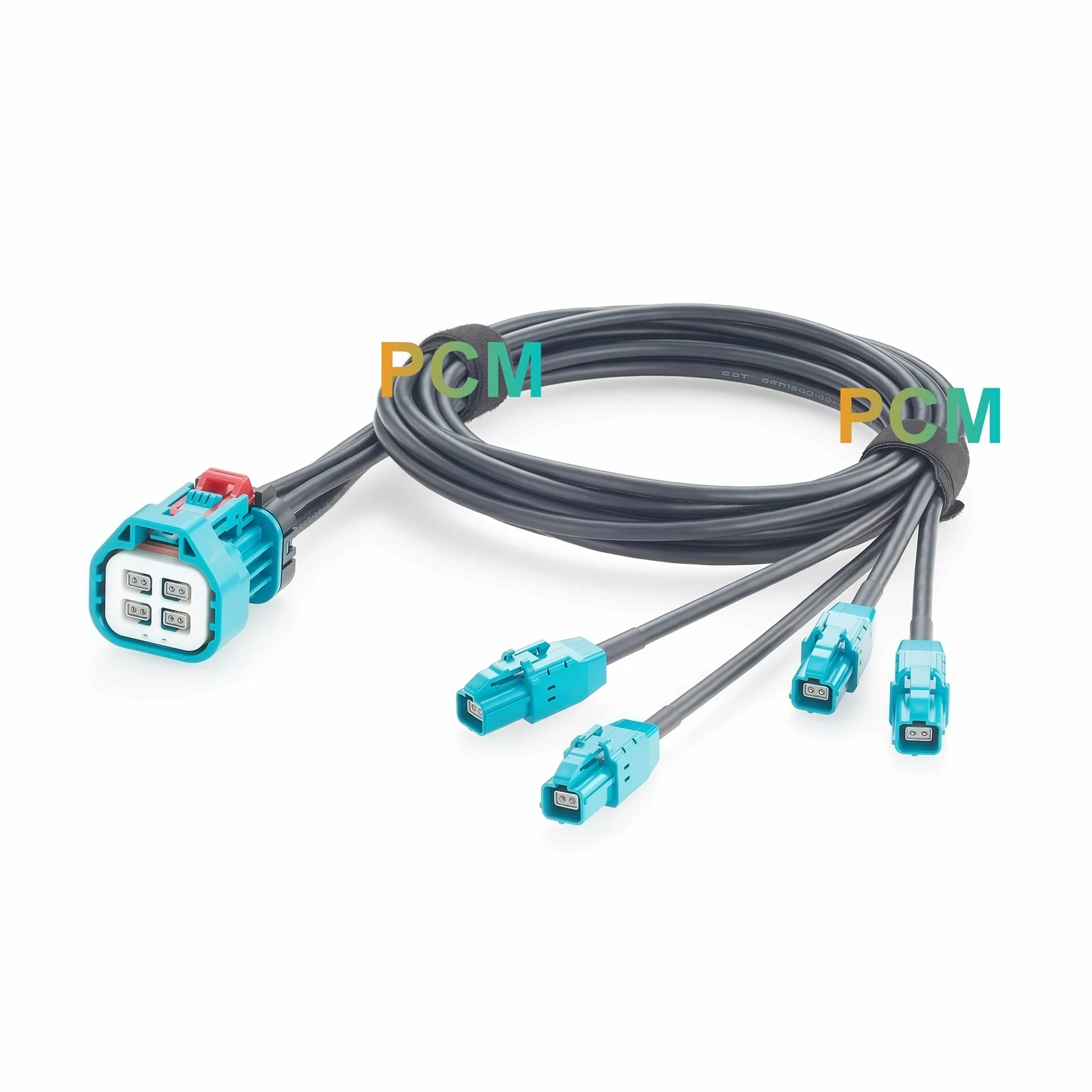
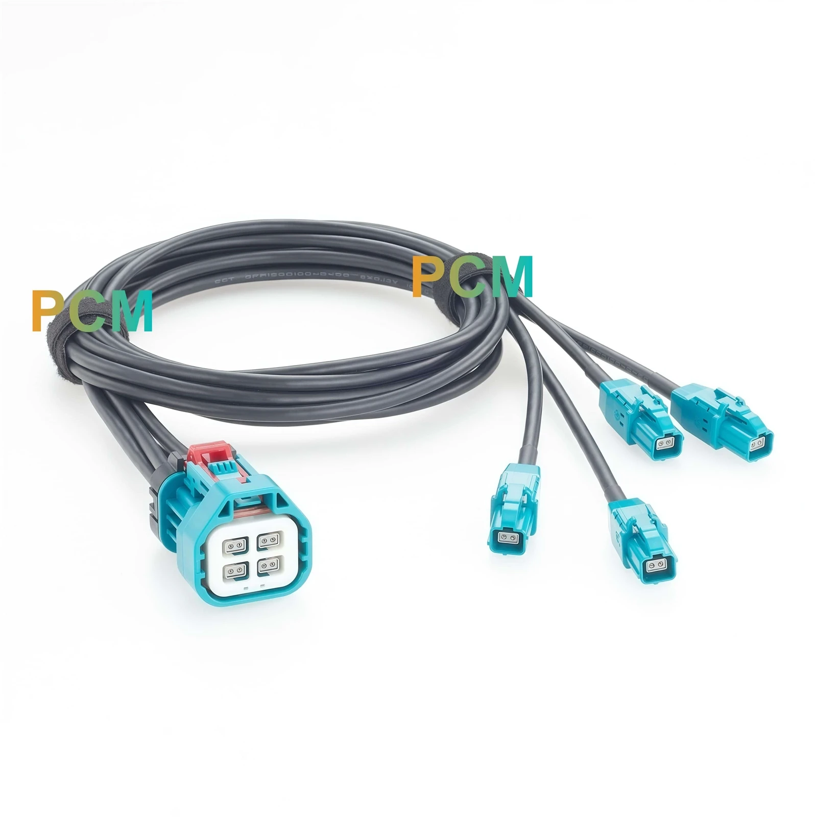
Straight Cable Exits With Separate Rear Entries
At the rear of P1, four cables enter the integrated connector through separate positions in the rear housing. Each cable continues to its own straight branch jack, with a black sleeve visible behind the branch connector body. The construction maintains separate cable paths along the harness, allowing branch spacing and routing direction to follow the installation layout beyond the grouped connector end.
Applications & Customer Value
Equipment Harness Integration
Independent branches accommodate connection points distributed across an assembly, while the equipment end remains concentrated at one mating location.
Prototype Development
Separate branch ends give engineers accessible connection points for channel identification, continuity checks and fault tracing.
Test Fixture Installation
The cable layout supports routing between connection points positioned around fixture plates, mounting structures and test stations.
Service Access Planning
Individual branches can be positioned near planned maintenance locations, subject to the approved routing dimensions and installation layout.
Product Features
Specified ECT Z Code Interfaces
The assembly uses ECT 818018063 at P1 and ECT 818019599 at four branch ends. Confirmed references support mating interface review and material control.
P1 IP67 Waterproof Construction
The integrated P1 connector is specified as IP67 Waterproof. The supplied drawing does not assign this rating to the branch connectors or the complete assembly.
Channel Shell Ground Connections
The wiring drawing defines a corresponding SHELL to SHELL GND path for each channel. These connections establish the grounding arrangement for termination and inspection.
Production Inspection Requirements
The drawing specifies 100% continuity testing, 500 VRMS minimum dielectric withstand and 110 N minimum cable retention, establishing measurable assembly verification criteria.
Customization Capabilities
Premier Cable supports:
Connector Customization
Connector type, gender, coding and housing design can be reviewed against mating part and installation requirements.
Cable Customization
Overall length, branch lengths, jacket, shielding and cable structure can be specified for the required routing and environment.
Electrical Customization
Pin assignment, wiring definition and circuit configuration can be developed from an approved schematic. Resistance value and power rating requirements are reviewed where applicable.
OEM Manufacturing
Drawing review, prototypes, mass production, labels and packaging are supported according to approved project specifications.
Product FAQ
Q1. Is this breakout cable an active signal splitter ?
The supplied drawing shows a wired interconnect without an active processing circuit. It does not establish amplification, switching or signal conversion functions.
Q2. Can another eight contact connector replace the integrated connector ?
An equal contact count does not establish interchangeability. Mating geometry, contact arrangement, coding and locking features must match the specified interface.
Q3. Can this cable connect to a particular vehicle or automotive Ethernet device ?
Vehicle and protocol compatibility are not confirmed in the supplied documents. Submit the equipment mating part number and electrical interface requirements for assessment.
Q4. Does the DC-5 GHz frequency range confirm a specific data rate ?
No. A data rate requires assessment against the intended protocol and applicable channel test requirements; frequency range alone is insufficient.
Q5. What information is needed for an OEM quotation ?
Send the mating connector references, routing dimensions, wiring diagram, quantity and inspection requirements. Include environmental, labeling and packaging specifications where applicable.

Hot Tags: ect z code 4 channel breakout cable, China ect z code 4 channel breakout cable manufacturers, suppliers, factory