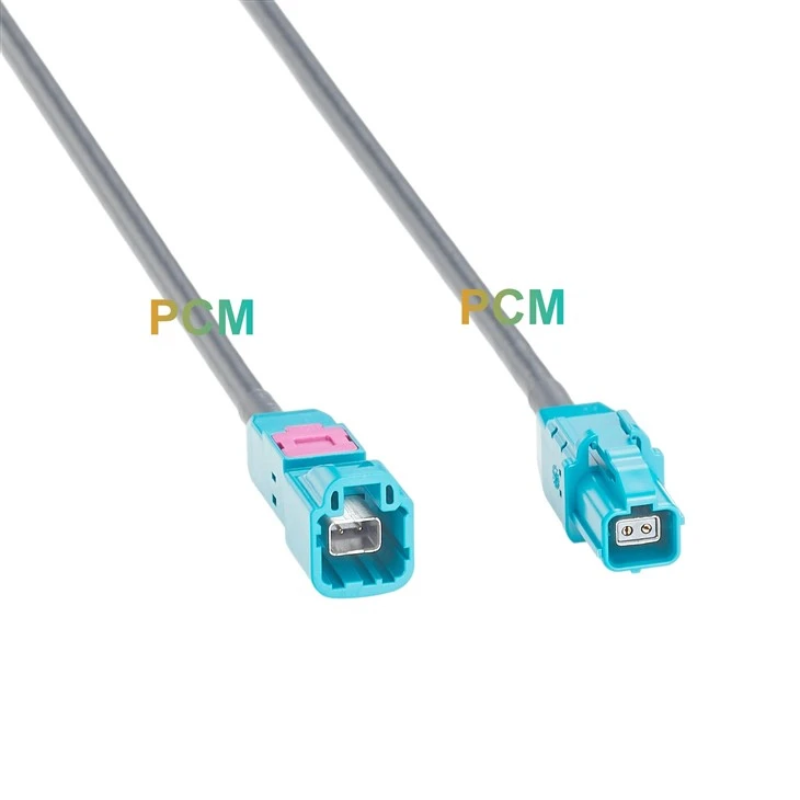
Product Specifications
| Parameter | Specification |
|---|---|
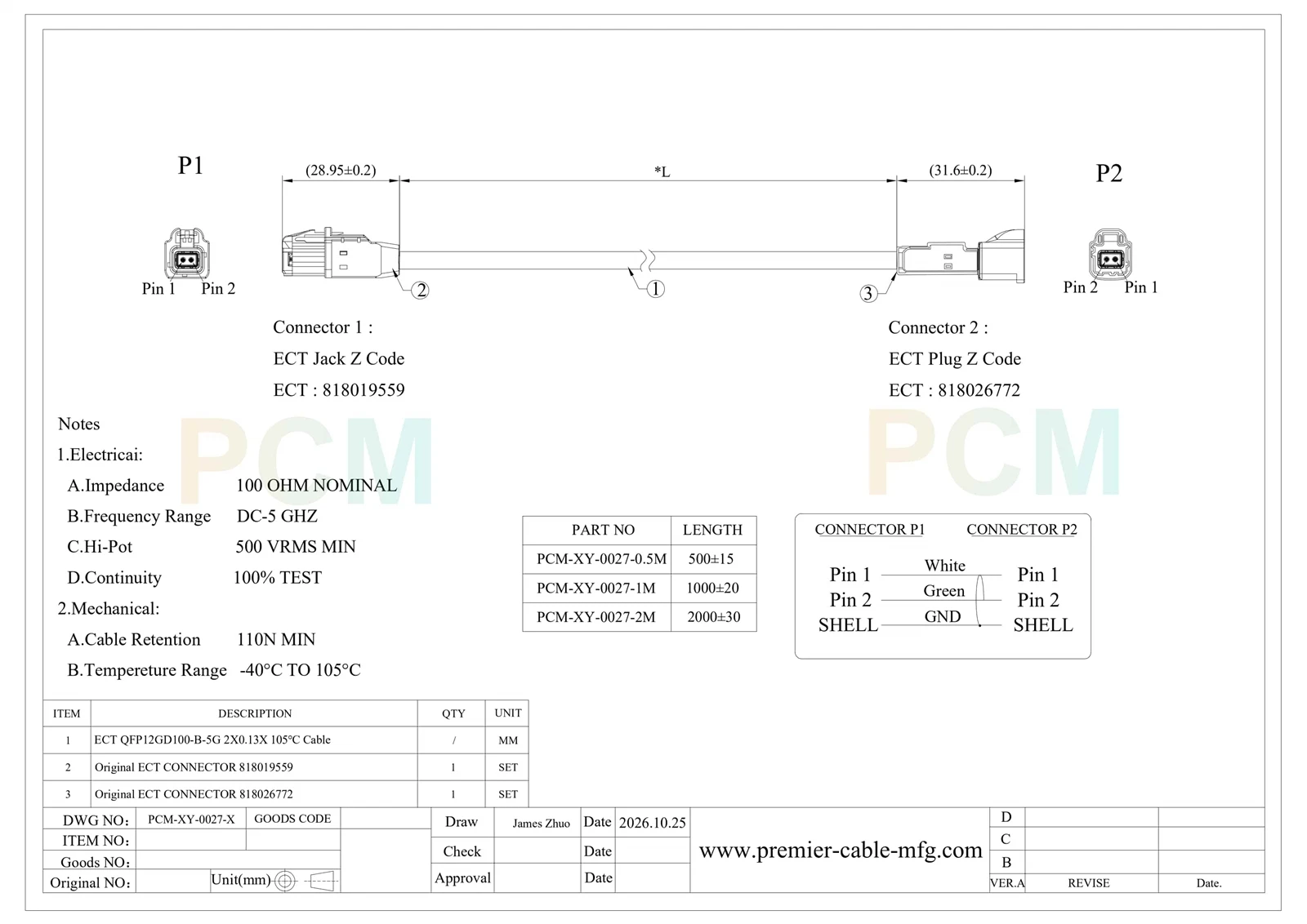
| Nominal Impedance | 100 Ω |
| Continuity Inspection | 100% tested |
| Frequency Range | DC to 5 GHz |
| Product Series | PCM-XY-0027 |
| Contact Count | 2 at each end |
| Temperature Range | −40°C to +105°C |
| Cable Retention | 110 N minimum |
| Dielectric Withstand | 500 VRMS minimum |
| Cable Model | ECT QFP12GD100-B-5G |
| Coding | ECT Z Code at both ends |
| P2 Connector | ECT 818026772 male plug |
| P1 Connector | ECT 818019559 female jack |
Male to Female Extension Structure
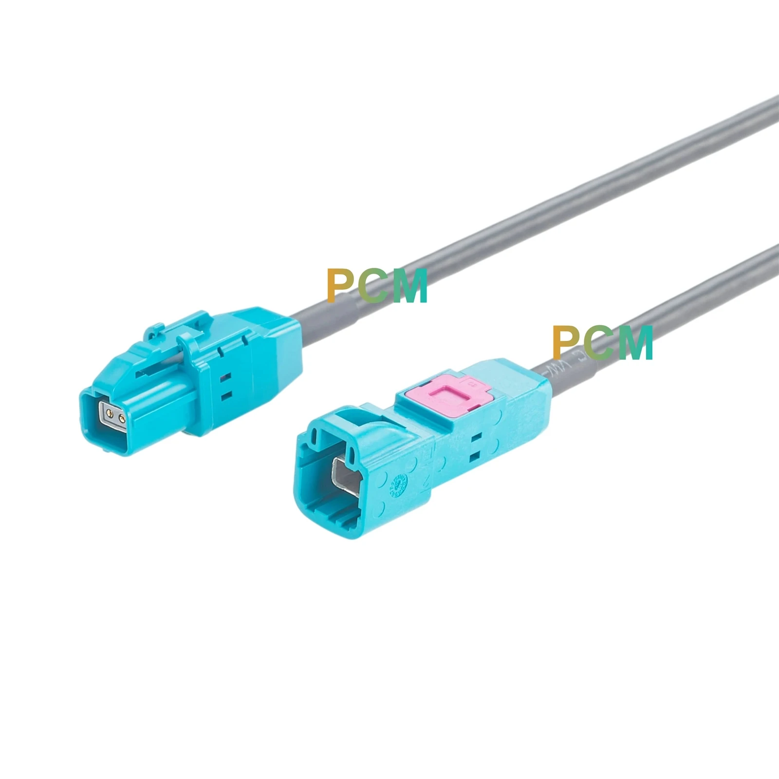
Complementary Jack and Plug Ends
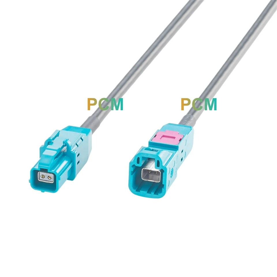
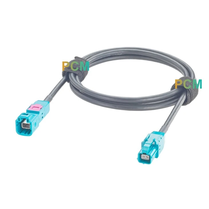
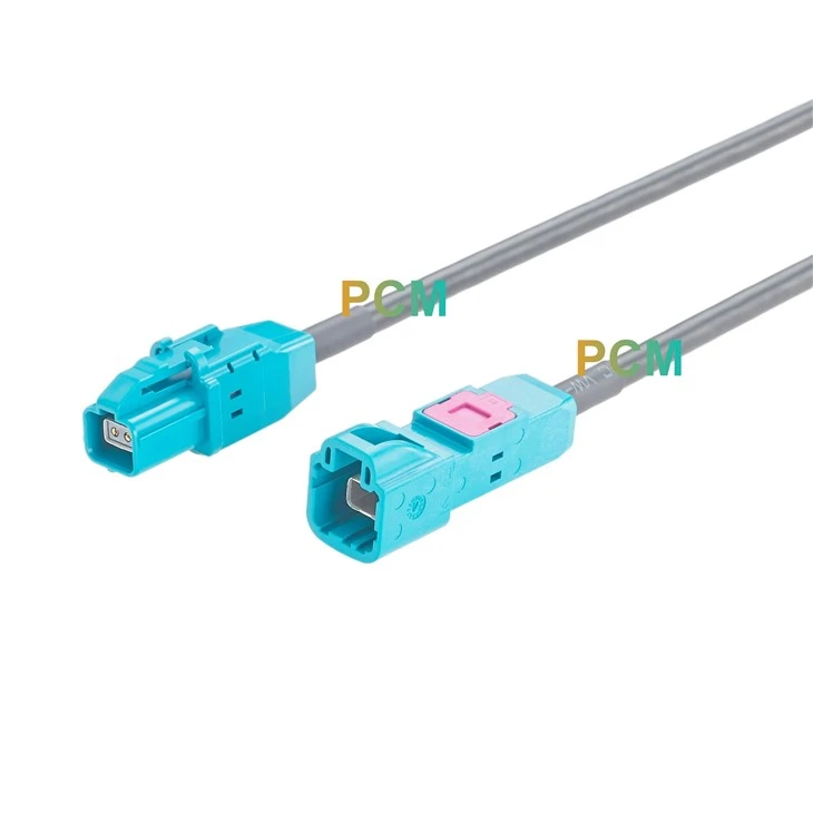
The assembly combines an ECT 818019559 female jack with an ECT 818026772 male plug. Each end has its own housing geometry, providing complementary interface genders within one cable assembly. This arrangement creates an extension section between confirmed mating parts, with the jack and plug positions selected according to the existing connection rather than introducing a branch or grouped connector.
Direct Contact Mapping
The wiring follows a direct correspondence between the two ends: P1 Pin 1 connects to P2 Pin 1 through the white conductor, and P1 Pin 2 connects to P2 Pin 2 through the green conductor. A separate GND path joins the connector shells. This documented arrangement defines the extension wiring without crossing the contacts, combining circuits or adding a signal distribution junction along the cable.
Straight Cable Exit Construction
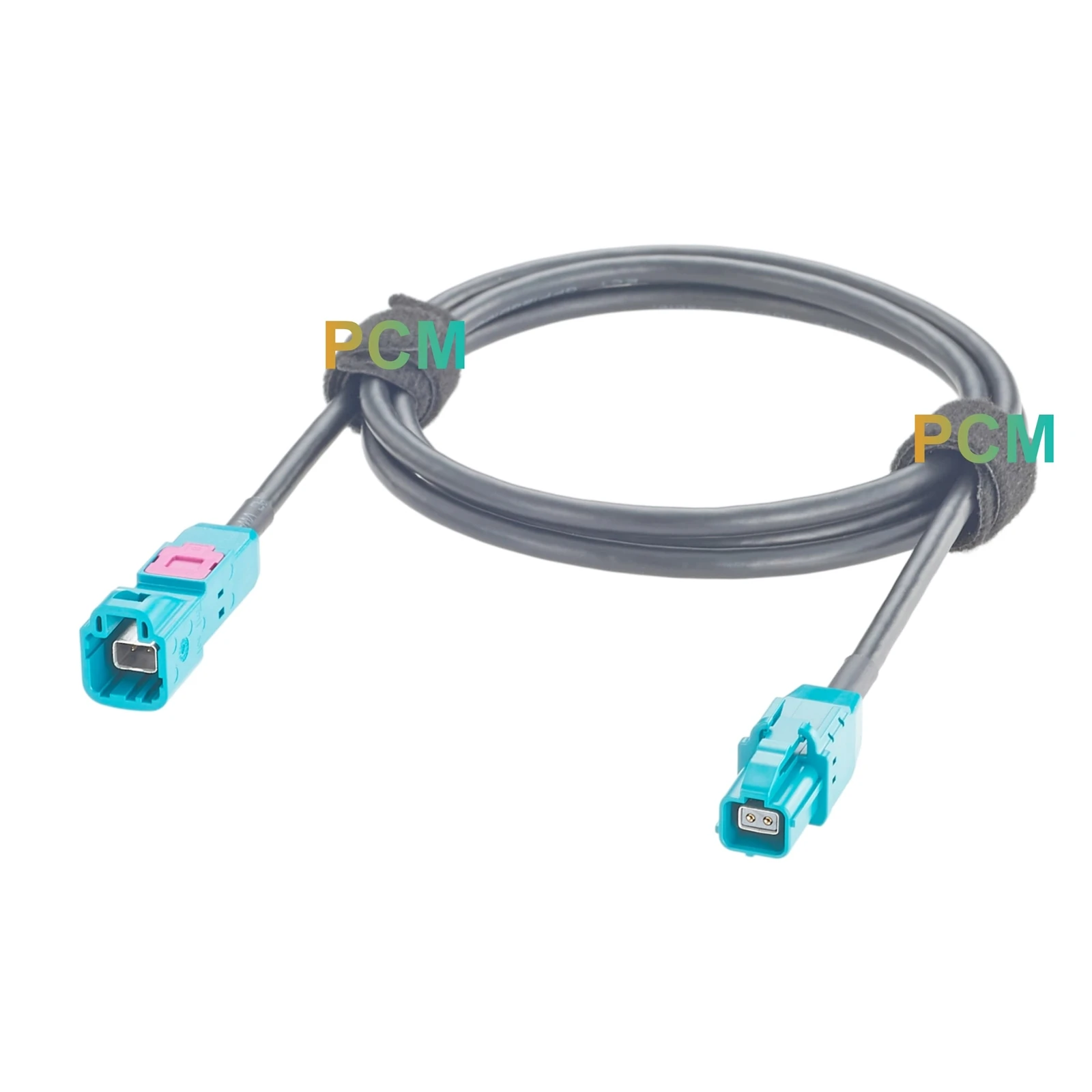
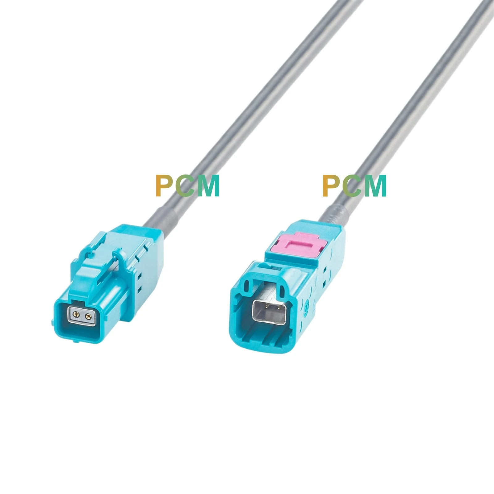
Both connectors use straight rear cable exits, with the cable continuing along the connector axis before following the installation route. The photographs show a black sleeve at each transition between the housing and cable. The two ends remain individually housed and connected by a single cable run, allowing their positions to follow the required spacing instead of being fixed within a rigid adapter body.
Applications & Customer Value
Equipment Layout Changes
Additional cable reach accommodates relocated connection points when the original harness no longer follows the required route.
Development Bench Access
An extended connection can bring the mating position closer to the work area, making setup changes and inspection more accessible.
Test Fixture Connections
The cable can bridge spacing between confirmed mating interfaces on a fixture, allowing connection placement to follow the mechanical layout.
Maintenance Interface Placement
The extension can move a connection toward an accessible service location, subject to available space and complete link requirements.
Product Features
Specified ECT Z Code Components
The drawing identifies ECT 818019559 and 818026772 as connector components. These references support mating-part verification and purchasing review.
Documented Shell Ground Connection
A dedicated GND connection electrically links the two connector shells. This defines the required grounding path for termination and continuity inspection.
Cable and Electrical Specifications
The assembly specifies ECT QFP12GD100-B-5G cable, 100 Ω nominal impedance and DC–5 GHz frequency range for assessment against connection requirements.
Electrical and Mechanical Criteria
The drawing requires 100% continuity testing, 500 VRMS minimum dielectric withstand and 110 N minimum cable retention, establishing measurable production checks.
Customization Capabilities
Premier Cable supports:
Connector Customization
Connector type, gender, coding and housing design can be reviewed against mating parts and installation requirements.
Cable Customization
Length, jacket, shielding and cable structure can be specified for the required routing and operating environment.
Electrical Customization
Pin assignment, wiring definition and circuit configuration can follow an approved schematic. Resistance value and power rating requirements are reviewed where applicable.
OEM Manufacturing
Drawing review, prototypes, mass production, labels and packaging are supported according to approved project specifications.
Product FAQ
Q1. Does this extension cable amplify or regenerate signals ?
The supplied drawing shows a passive wired assembly without an amplification or regeneration circuit. Its function is to extend the physical connection path.
Q2. How does this cable differ from a rigid male to female adapter ?
A rigid adapter fixes both interfaces within one body. A cable extension allows the two connection positions to be separated along a defined route.
Q3. Will it work with any turquoise Z Code connector ?
Housing color and coding alone do not confirm compatibility. Check the exact mating connector model, contact system and mechanical interface.
Q4. What determines the maximum usable extension length ?
The permitted length depends on the complete link, including the intended protocol, existing cable, connector interfaces and electrical limits. The supplied drawing does not establish a universal maximum.
Q5. What information is required to order an OEM extension cable ?
Supply the mating part references, required length, wiring requirements, quantity and acceptance criteria. Include environmental, labeling and packaging details where applicable.

Hot Tags: ect z code extension cable 818019559, China ect z code extension cable 818019559 manufacturers, suppliers, factory