

Product Specifications
| Parameter | Specification |
| Characteristic impedance | 90Ω |
| Cable outer diameter | 4.6mm |
| Frequency specified in drawing | 480MHz |
| PCM drawing number | PCM-ZC-0234 |
| Axial pull strength | 110N minimum |
| Insulation resistance | 100MΩ minimum |
| Operating temperature per drawing | −40°C to 105°C |
| Dielectric withstand voltage | 500V RMS minimum |
| Insertion and extraction durability | 25 cycles minimum |
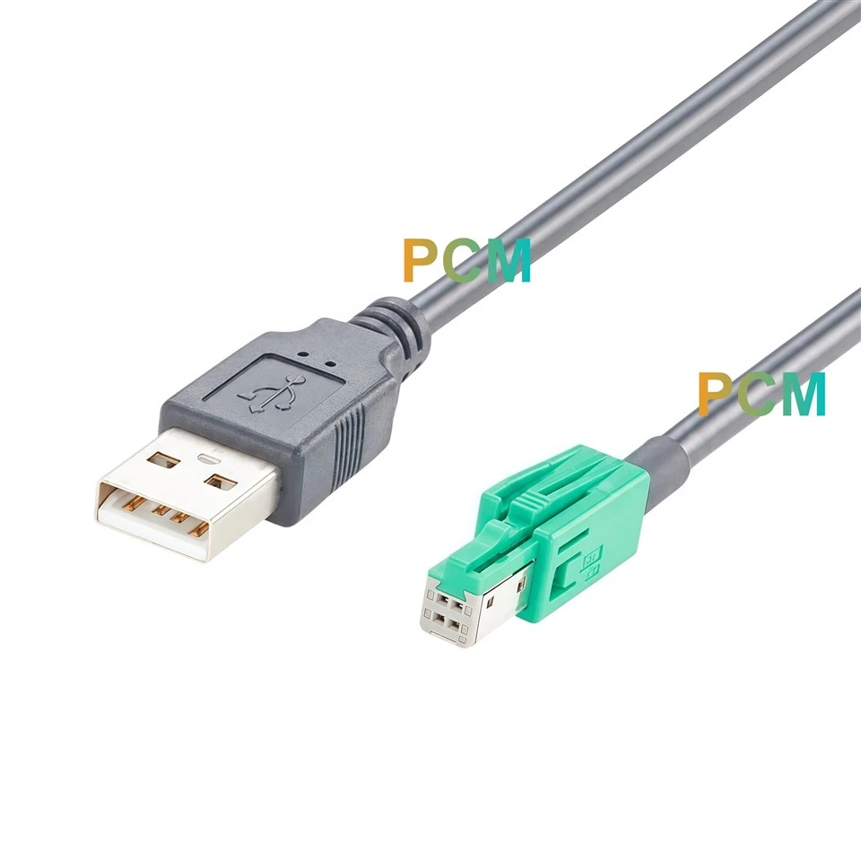
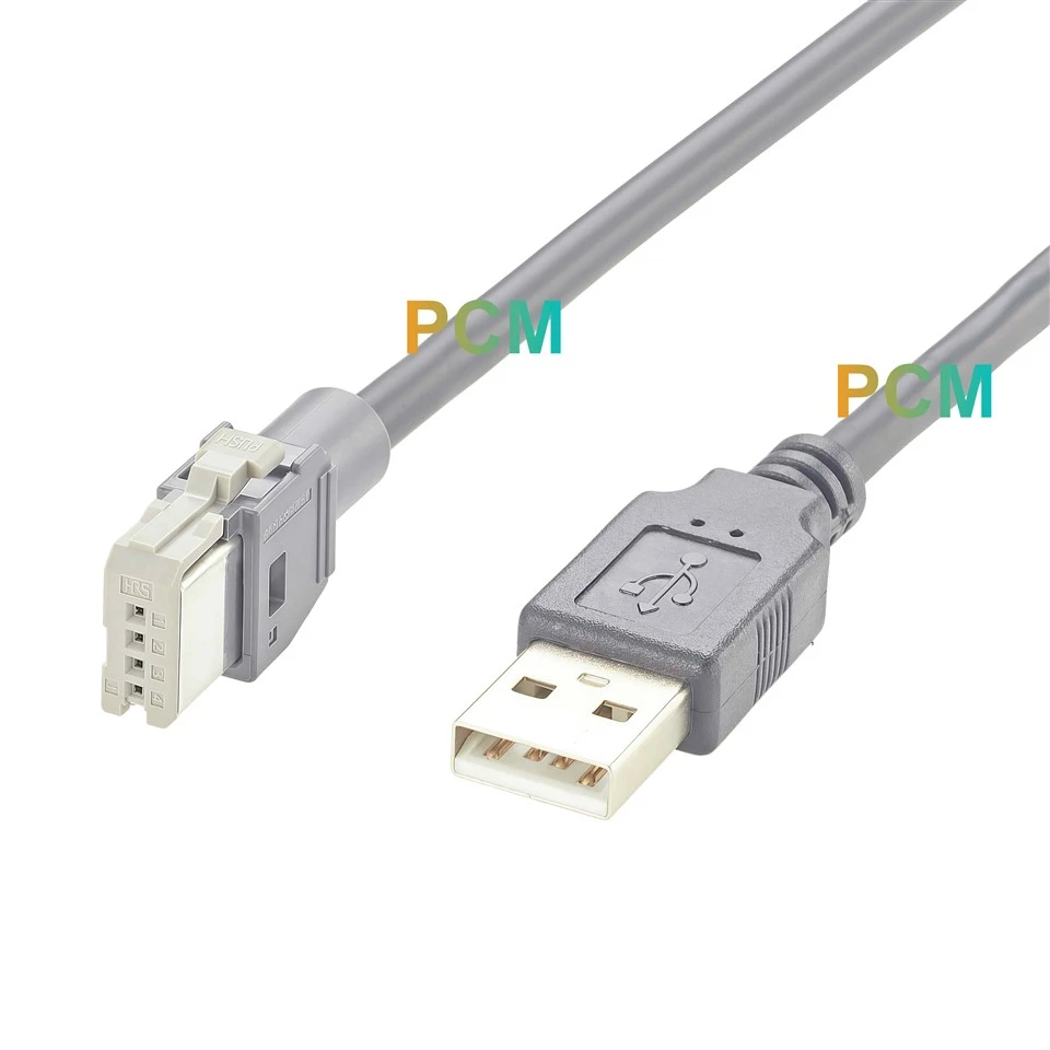
| Host connector | USB 2.0 Type A male |
| Hirose end sleeve | Black, 5.0mm outer diameter and 20mm long |
| Controlled cable length | 2m ± 0.03m between drawing reference points |
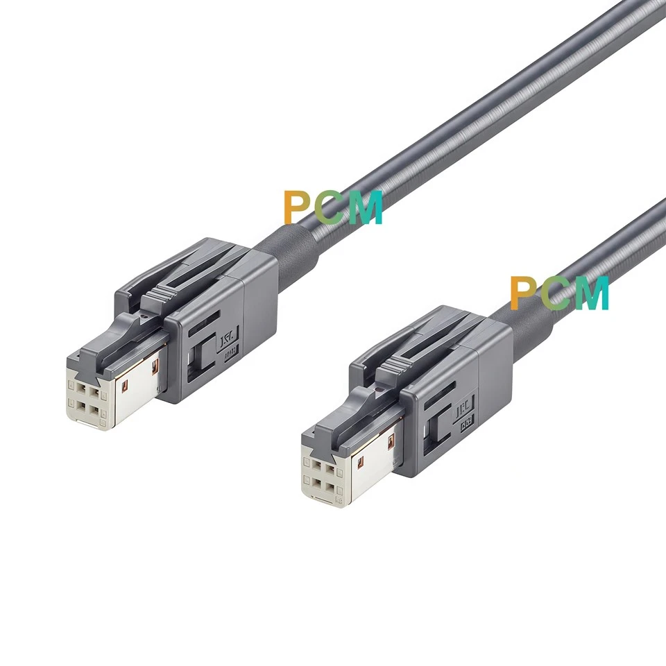
| Module connector | Hirose GT17H Standard, four contacts in one row |
| Hirose shell | Original Hirose GT17HS-4S-HU, dark gray housing |
| Hirose connector insert | GT17H-4S-2C, light gray Standard insulation case |
| Cable construction | Shielded USB 2.0 cable with one 26AWG pair and two 24AWG conductors |
Connecting a GT17H Module to a USB Host

Keep the Module Connected Between Test Runs
Once the Hirose connector is latched into the module, operators can connect or disconnect the USB Type A plug at the host without reaching into the fixture. This is useful when the module sits behind a bracket or when a test setup moves between a development computer and a validation station. The molded USB grip gives operators a place to hold the plug during removal, and the strain relief supports the cable where it leaves the plug. Leave enough room around the host receptacle to grasp the plug with neighboring ports occupied.
Match the Light Gray Insert to the Equipment Port
The module end uses the light gray GT17H-4S-2C insert inside the dark gray GT17HS-4S-HU housing. The insert determines the Standard mating profile. If the module documentation lists only the housing or describes the port simply as a four position Hirose connector, compare the mating face and equipment part number before ordering. This is especially useful on benches that also handle the brown GT17H A Key variant. The two part numbers let buyers specify both the outer housing and the intended key. www.hirose.com


Trace USB Power and Data Before Powering the Module
The USB plug assigns VCC to pin 1, D− to pin 2, D+ to pin 3 and GND to pin 4. Each signal reaches the same numbered contact on the Hirose end. Use that map when reviewing a new module revision or troubleshooting a unit that the host fails to recognize. The cable uses a 26AWG data pair and separate 24AWG conductors for power and ground. The metal shells have their own continuity path, so a fixture can check that connection separately from USB ground on pin 4.
Route the Lead With the Fixture Closed
The 2m span is measured between the reference points on the drawing and has a tolerance of ±0.03m. When the host and module are on different sides of the bench, measure the route along the fixture and through any guides. At the module end, allow space behind the 20mm sleeve and above the PUSH tab. Check both clearances with the cover or bracket in its final position. If the module tray slides out, verify that the cable can follow the tray through its travel without pulling on the USB plug or the Hirose connector.

Automotive USB Test Applications
| Test task | How PCM-ZC-0234 is used |
|---|---|
| USB device recognition | Connect a compatible infotainment or media module to a bench computer and check whether the host detects it. |
| Service diagnostics | Test a compatible module on the bench to isolate it from the vehicle harness while checking USB communication. |
|
Revision Comparison |
Keep host and cable setup consistent while comparing modules with the GT17H Standard interface and USB pin assignment. |
Product Drawing

Product FAQ
Can I connect this cable directly to a computer ?
Yes. The USB Type A male plug fits a Type A host receptacle. The module at the other end must support USB device operation and use the pin assignment shown above.
Which GT17H port mates with the module end ?
Use a port that mates with the single row Hirose GT17H Standard profile. The light gray insert is GT17H-4S-2C, and the dark gray outer housing is GT17HS-4S-HU. www.hirose.com
Does the cable carry USB power as well as data ?
Yes. Pin 1 carries VCC and pin 4 carries GND. Pins 2 and 3 carry USB data. Available current depends on the host port and the connected module.
Does 480MHz specify the USB data rate ?
480MHz is the frequency value listed on the assembly drawing. Confirm the supported USB data rate with the intended host and module connected.
What information should I provide when requesting a sample ?
Send PCM drawing number PCM-ZC-0234 and estimated quantity. For a different length, include the target dimension and the two measurement points.

Hot Tags: hirose gt17h 4 pin automotive usb 2.0 cable, China hirose gt17h 4 pin automotive usb 2.0 cable manufacturers, suppliers, factory