

Product Specifications
| Parameter | Specification |
| Nominal impedance | 100Ω |
| Cable type | DACAR 535 |
| Frequency range per drawing | DC to 2GHz |
| PCM part number | PCM-ZC-0249 |
| Contact positions | Four per end |
| Cable retention | 110N minimum |
| Continuity test requirement | Every assembly |
| Temperature range per drawing | −40°C to +105°C |
| Dielectric withstand voltage | 500V RMS minimum |
| Connector at each end | Hirose GT32-4DS-1.5C |
| End configuration | Hirose GT32 D Key to D Key |
| Connector reference dimension | 28.4mm ± 0.15mm at each end |
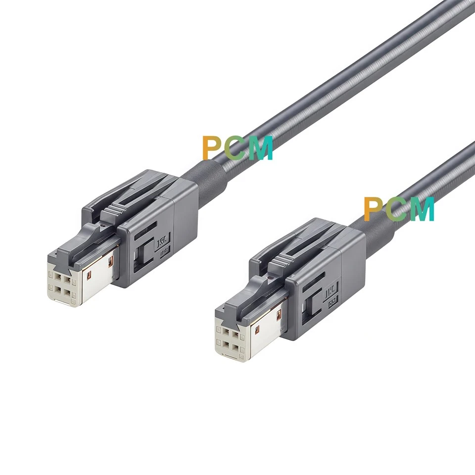
| Shell at each end | Original Hirose GT32-4DS-HU(D), black |
| Cable exit sleeve | Black, 5.0mm outer diameter and 20mm long |
| Controlled cable length | 2000mm ± 20mm between the drawing reference points |
| Wiring | Straight through by contact number with shell continuity |
What to Check Before Specifying the D Key Cable

Identify the Key From the Shell Number
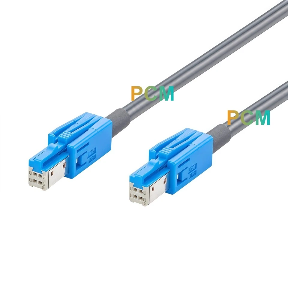
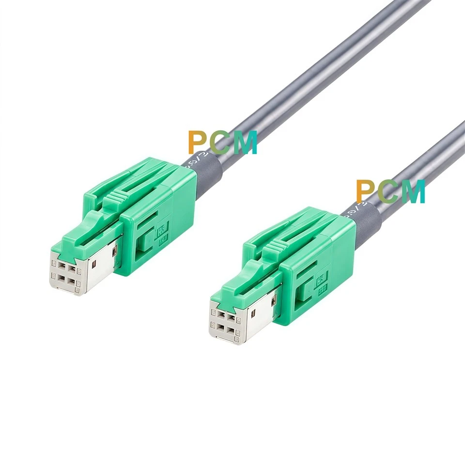
Both ends carry the original black Hirose GT32-4DS-HU(D) shell. The D suffix identifies the mating profile, which is the detail to check when a program uses more than one GT32 variant. The drawing lists GT32-4DS-1.5C separately as the connector at each end. If an equipment list gives only that number, confirm the shell number and mating port before ordering. This is particularly useful when comparing the black D Key version with the dark gray Standard version in photos or sample bins.
Check the Signal Assignment at Both Modules
Pin 1 stays on pin 1 from one module to the other, and the same pattern applies through pin 4. When two module revisions share the Hirose GT32 D Key profile, compare their pin tables to confirm that each signal reaches its intended contact. The drawing shows a separate path between the metal shells, so a continuity fixture can check that path independently of the four conductors. Use the mating face views to establish contact orientation before comparing the cable map with the equipment drawings.


Allow Space to Connect and Release Both Ends
Check the cable route with the module brackets and neighboring harnesses in place. A route can reach both ports and still leave too little space above a Hirose latch for a technician to release it. Behind each connector, the 20mm sleeve also occupies part of the space before the cable turns. Use the 28.4mm connector reference dimension and the controlled cable span to check the installed layout. If a module must slide out for service, verify that the cable can move with it without pulling on either end.
Review DACAR 535 Against the Link Requirements
The assembly drawing specifies DACAR 535, 100Ω nominal impedance and a frequency range from DC to 2GHz. Keep the cable designation with the electrical requirements when comparing supplier quotations or reviewing a length change. For a specific vehicle data link, assess the assembly with the intended module interfaces and mating connectors. The frequency range is an electrical specification for the assembly. The supported protocol and data rate depend on how the complete link performs.

Where the USB Female End Fits
| Application | How the cable is used |
|---|---|
| Infotainment module integration | Connect a head unit and a remote infotainment module with mating Hirose GT32 D Key ports and compatible signal assignments. |
| Vehicle harness layout trials | Route the 2000mm assembly through a prototype to check reach, clip locations and access to both latches before finalizing the harness. |
| Integration benches | Connect modules mounted at separate positions and check communication with the connector and wiring configuration planned for the vehicle. |
Product Drawing

Product FAQ
How do I identify the D Key version when ordering ?
Look for GT32-4DS-HU(D) on both shell callouts. The black shell is a visual cue, and the full Hirose part number identifies the mating profile.
Can either end of the cable connect to either module ?
Yes, when both modules have mating Hirose GT32 D Key ports and their signal assignments agree with the cable map. The connector configuration is identical at both ends.
Does the 2000mm cable length include the connectors ?
The drawing specifies 2000mm ± 20mm between the marked reference points near the cable exits. Use the separate connector dimensions when checking the total installation space.
What does the 500V RMS specification mean ?
It is the minimum dielectric withstand test voltage listed on the drawing. Confirm the operating voltage against the requirements of the equipment interface.
What information should I send for a quotation ?
Reference PCM-ZC-0249 and include the estimated quantity. If your project requires a different configuration, send the mating Hirose part number at each end, the target cable length and the required wiring.

Hot Tags: hirose gt32 d key to d key cable, China hirose gt32 d key to d key cable manufacturers, suppliers, factory