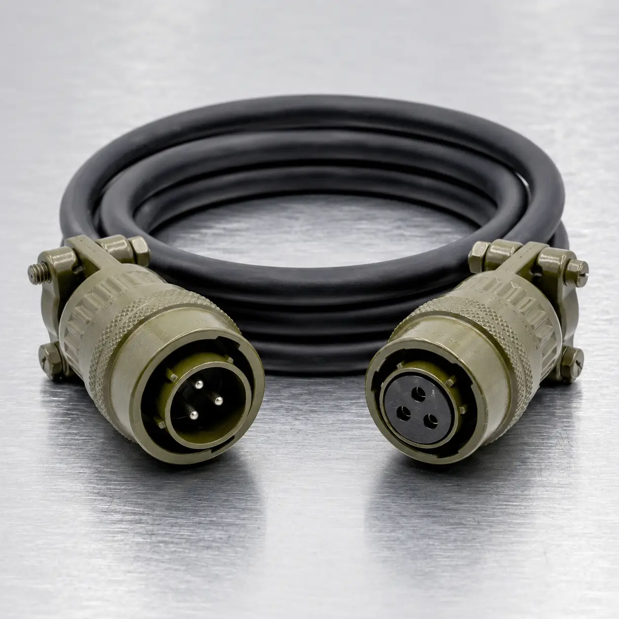


MS3116F8-4 Cable Assembly at a Glance
The MS3116F8-4P to MS3116F8-4S cable assembly is a compact four-circuit interconnect built around MIL-DTL-26482 Series I-style solder connectors. It combines a small shell size, quick bayonet engagement and rear cable strain relief for equipment connections that may require regular installation, removal or maintenance access.
An MS3116F8-4P straight plug with pin contacts is fitted at one end. The opposite end carries an MS3116F8-4S straight plug with socket contacts. The finished cable is manufactured according to the required pin assignment, length, conductor construction and operating environment.
This product should be specified as a custom equipment cable rather than treated as a universal extension lead. Connector compatibility and contact-to-contact wiring must be confirmed before production.
Why Select the MS3116F8-4 Configuration?
| Compact Interface | Shell size 8 provides a small circular connection for equipment with limited panel and cable-routing space. |
| Four Circuits | The 8-4 insert arrangement provides four contact positions for control, sensing, communication or low-current supply functions. |
| Quick Coupling | The bayonet interface is suited to equipment that must be connected and disconnected without repeatedly rotating a threaded coupling nut. |
| Cable Support | Class F rear hardware provides mechanical support near the cable exit and helps reduce stress on the solder terminations. |
| Custom Construction | The conductor layout, shielding, jacket, identification and external protection can be selected for the target equipment. |
Connector Identity Card
| End 1 | MS3116F8-4P straight cable plug |
| End 1 Contact Form | Pin contacts |
| End 2 | MS3116F8-4S straight cable plug |
| End 2 Contact Form | Socket contacts |
| Connector Platform | MIL-DTL-26482 Series I style |
| Shell and Layout | Shell size 8 with 8-4 insert arrangement |
| Contact Population | Four size 20 solder contacts |
| Service Class | Class F with environmental-resisting grommet and strain relief |
| Locking Method | Three-point bayonet coupling |
Choose a Cable Build by Function
The same connector combination can be used with different internal cable constructions. The appropriate build depends on what the four circuits must carry.
| Build Type | Typical Construction | Selection Considerations |
| Control Harness | Four individually color-coded conductors | Confirm switching voltage, conductor identification and equipment pin assignment. |
| Sensor Lead | Shielded four-core cable or selected paired conductors | Define signal type, noise exposure, shield coverage and shield termination. |
| Low-Current Supply | Supply, return and auxiliary conductors | Confirm operating current, cable length, voltage drop and simultaneous loading. |
| Mixed-Function Cable | Power and control conductors within one jacket | Review conductor grouping and possible interference between power and sensitive circuits. |
The connector arrangement does not determine which position is power, ground, input or output. All circuit functions must be defined by the equipment drawing.
Four Contacts, Customer-Defined Functions
The four positions are identified as A, B, C and D. A direct cable may use A-to-A, B-to-B, C-to-C and D-to-D continuity, but this is not automatically assumed during production.
Available circuit configurations include:
- One-to-one contact continuity
- Crossed contact assignments
- Two-wire or three-wire builds with unused positions
- Common supply or return connections
- Customer-defined shield or chassis connection
- Circuit identification matched to an existing equipment harness
A contact map should show the required relationship between both connector ends. Wire colors may be included as an additional production reference, but color alone should not replace the electrical pinout.
Cable Diameter and Class F Strain Relief
The rear strain-relief assembly is one of the main reasons to select the F service class. It supports the cable behind the connector and reduces direct pulling or bending force at the soldered contacts.
Correct operation depends on matching the cable outside diameter to the rear hardware. Cable selection should therefore consider more than conductor count.
| Item to Confirm | Why It Matters |
| Cable Outside Diameter | Determines whether the strain-relief components can grip and support the cable correctly. |
| Cable Flexibility | Affects installation routing and repeated bending near the connector exit. |
| Minimum Bend Radius | Helps prevent conductor or shield damage in compact installations. |
| Jacket Hardness | Influences the effectiveness of the mechanical clamp and long-term cable support. |
| Movement Frequency | Determines whether standard, flexible or high-flex cable construction is appropriate. |
Using the Bayonet Interface in Equipment
The bayonet coupling system supports quick mating and unmating. The connector should first be aligned with the equipment receptacle keyway, pushed into engagement and then rotated until the coupling is fully locked.
The cable should not be used to pull, rotate or unlock the connector. Coupling and uncoupling force should be applied to the connector body to avoid transferring unnecessary load to the cable entry.
For installations requiring frequent service access, allow sufficient free cable length behind the connector so the harness is not placed under tension when the equipment is opened or repositioned.
Available Materials and Finishing
| Design Element | Available Direction |
| Conductor Size | Selected according to signal type, current, voltage drop and connector compatibility |
| Cable Shield | Unshielded, foil shield, braided shield or combined shielding |
| Jacket | PVC, PUR, rubber or another customer-approved material |
| External Covering | Braided sleeving, abrasion covering or flexible conduit |
| Connector Exit | Class F strain relief with optional heat-shrink reinforcement |
| Identification | End labels, cable number, equipment reference or serial marking |
Mating Receptacle Must Be Confirmed
The P and S suffixes describe the contact form inside each connector. They do not mean that the socket-contact end is a panel receptacle. Both ends of this assembly use an MS3116 straight-plug body.
The two cable-end connectors are therefore normally connected to separate equipment receptacles rather than plugged directly into each other.
The equipment interface should be checked for all of the following:
- MIL-DTL-26482 Series I-compatible interface
- Shell size 8
- 8-4 contact arrangement
- Complementary contact form
- Matching key and insert orientation
An additional W, X, Y or Z suffix indicates an alternate insert rotation. A normal-orientation connector should not be assumed compatible with an alternate-rotation interface.
Build Information Sheet
| Required Information | Customer Input |
| Quantity | Prototype, sample, batch quantity or annual demand |
| Finished Length | Connector reference point to connector reference point, including tolerance |
| Circuit Definition | Contact mapping for A, B, C and D |
| Electrical Function | Power, return, control, sensor or communication function of each circuit |
| Cable Requirement | Wire gauge, jacket, shielding, flexibility and temperature requirement |
| Installation Conditions | Static, portable, frequently disconnected, vibrating or moving installation |
| Mating Hardware | Equipment receptacle part numbers or clear mating-face photographs |
| Marking and Records | Labels, serial numbers, approved drawing or electrical test report |
Example Order Definitions
Example A - Instrument Control Cable: 2 m finished length, four individually identified conductors, straight-through wiring, overall braided shield and equipment labels at both ends.
Example B - Portable Test Lead: flexible jacket, frequent mating requirement, custom crossed pinout, serial-number marking and additional heat-shrink reinforcement behind the strain relief.
Example C - Replacement Equipment Harness: construction matched to an existing sample, wiring verified from the equipment schematic and cable length reproduced from the original installation.
These examples illustrate possible configurations only. The final assembly should be produced from the customer-approved cable definition.
Hot Tags: ms3116f8-4p to ms3116f8-4s 4-contact bayonet cable assembly, China ms3116f8-4p to ms3116f8-4s 4-contact bayonet cable assembly manufacturers, suppliers, factory