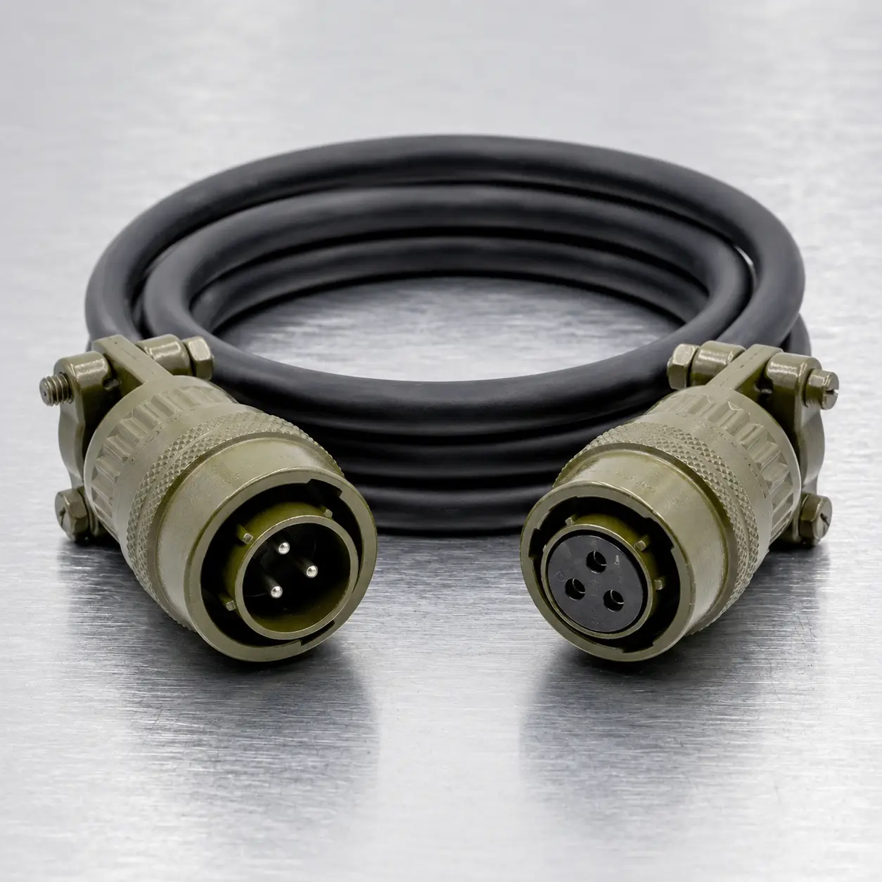


Different Cable-Entry Designs at Each End
The MS3116F12-4P to MS3116E12-4S cable assembly combines two straight bayonet plugs with different rear cable-entry constructions. The pin-contact end uses Class F strain-relief hardware, while the socket-contact end uses a more compact Class E grommet and clamping-nut arrangement.
This asymmetric configuration is useful when one side of the installation requires additional cable support and the opposite side must fit within a more restricted equipment space. It can be manufactured for control, sensor, feedback, low-current power or mixed electrical circuits.
The connector models define the physical interfaces but do not establish the finished cable length, conductor assignment or electrical function. Each assembly is built according to an approved customer pinout and cable specification.
End-to-End Construction
| Feature | Pin-Contact End | Socket-Contact End |
| Part Number | MS3116F12-4P | MS3116E12-4S |
| Body Style | Straight cable plug | Straight cable plug |
| Contact Form | Four pin contacts | Four socket contacts |
| Rear Construction | Environmental grommet with strain relief | Environmental grommet with clamping nut |
| Installation Benefit | Additional support against cable pulling and bending | Shorter and less complex rear cable-entry arrangement |
The cable can be installed with the Class F end facing the side exposed to handling, movement or unsupported cable weight. The Class E end may be used where the harness is routed directly into protected or space-constrained equipment.
12-4 Interface Definition
| Connector Platform | MIL-DTL-26482 Series I style |
| Shell Size | 12 |
| Insert Arrangement | 12-4 |
| Contact Quantity | 4 |
| Contact Positions | A, B, C and D |
| Contact Size | Size 16 |
| Termination | Solder termination |
| Coupling | Three-point bayonet coupling |
| Typical Wire Range | 16–20 AWG, subject to the selected connector and cable build |
| Reference Contact Current | Up to 13 A per size 16 contact, subject to complete assembly conditions |
The 12-4 designation is an insert-arrangement code. It should not be interpreted as a twelve-contact connector. The arrangement contains four electrical positions.
Why Use an F-to-E Cable?
Using Class F at both ends may add unnecessary rear hardware where installation space is restricted. Using Class E at both ends may provide insufficient mechanical support where one side of the cable is frequently handled or exposed to movement.
The mixed-service-class configuration allows each cable end to be adapted to its installation condition:
| Installation Condition | Recommended End | Reason |
| Portable or handled equipment | Class F end | Rear strain relief provides additional mechanical cable support. |
| Fixed protected equipment | Class E end | Compact cable entry is suitable where external strain is limited. |
| Restricted rear clearance | Class E end | Reduced rear hardware can simplify routing near enclosures or panels. |
| Unsupported cable drop | Class F end | The strain-relief assembly helps manage cable weight near the termination. |
Circuit Definition Before Manufacturing
Contact positions A, B, C and D identify physical cavities only. They do not specify positive voltage, return, protective ground, signal input or signal output.
A direct cable may be wired A-A, B-B, C-C and D-D. However, the following alternatives can also be manufactured:
- Crossed contact assignments
- Partially populated two-wire or three-wire construction
- Shared power or common return circuits
- Mixed conductor gauges for different circuit loads
- Shield drain or chassis connection
- Replacement wiring matched to existing equipment
Production should be based on a customer-approved pinout table or electrical drawing. A continuity check of an existing cable may also be used when the original documentation is unavailable.
Cable Diameter Must Suit Both Ends
Because the two connector ends use different rear hardware, cable outside diameter must be reviewed against both assemblies. A cable that works with the Class F strain relief may not automatically provide the correct fit at the Class E clamping nut.
| Design Item | Review Requirement |
| Finished Cable Diameter | Must fit the sealing and clamping components at both connector ends. |
| Jacket Compressibility | Must allow secure clamping without cutting or permanently deforming the jacket. |
| Cable Flexibility | Should match the routing radius and movement expected near the Class F end. |
| Shield Construction | Foil, braid and drain-wire choices affect the final cable diameter and termination method. |
| External Sleeving | Should normally begin behind the connector hardware rather than interfere with the cable clamp. |
Cable Construction Menu
| Component | Available Configuration |
| Finished Length | Manufactured to the specified connector-to-connector reference length and tolerance |
| Conductors | Uniform or mixed conductor sizes selected for the electrical circuits |
| Wire Identification | Color coding, printed wire numbers or heat-shrink markers |
| Shielding | Unshielded, overall foil shield, braided shield or combined shielding |
| Outer Jacket | PVC, PUR, rubber or customer-approved special material |
| Mechanical Covering | Braided sleeving, abrasion covering or flexible protective conduit |
| Product Identification | Connector-end labels, equipment references, serial numbers or customer part numbers |
Typical Installation Arrangement
Class F pin end: suitable for the side where the cable may be handled, moved, suspended or exposed to repeated bending. The strain-relief hardware should be positioned so that cable load is transferred to the connector rear assembly rather than directly to the solder joints.
Class E socket end: suitable for a fixed equipment side where the cable enters a protected enclosure, cabinet or instrument and is secured by separate cable management.
This direction is not mandatory. The final orientation should follow the actual installation, available rear clearance and location of mechanical cable loads.
Compatibility Is Determined at the Equipment Interface
Both ends use an MS3116 straight-plug body. The P and S suffixes indicate pin and socket contacts; they do not mean that the socket-contact connector is a panel receptacle.
The two cable-end connectors are normally intended to mate with separate equipment receptacles rather than directly with each other. Each equipment interface should be checked for:
- MIL-DTL-26482 Series I-compatible bayonet interface
- Shell size 12
- 12-4 insert arrangement
- Complementary pin or socket contact form
- Matching normal or alternate insert rotation
Connector versions carrying a W, X, Y or Z suffix use alternate insert positioning. Complete equipment-side connector part numbers should be supplied before production whenever possible.
Information Needed for Quotation
| Quotation Item | Information to Provide |
| Quantity | Sample, prototype, production quantity or estimated annual requirement |
| Cable Length | Required finished length and acceptable tolerance |
| Contact Map | Required wiring for positions A, B, C and D |
| Electrical Load | Voltage, normal current, peak current and signal type for each circuit |
| Cable Construction | Wire gauge, shielding, jacket, flexibility and temperature requirements |
| Installation Direction | Which equipment side requires the Class F strain-relieved connector |
| Mating Connectors | Complete part numbers or clear photographs of both equipment interfaces |
| Documentation | Required drawing, inspection record, cable labels or test report |
Asymmetric Assembly Inspection
Inspection of this cable includes separate checks for the two rear connector constructions. The Class F end is reviewed for strain-relief fit and cable support, while the Class E end is checked for correct grommet and clamping-nut assembly.
| Inspection Area | Verification |
| Connector Identification | Correct F/P and E/S connector models installed at the specified ends |
| Circuit Verification | Point-to-point continuity checked against the approved pinout |
| Fault Detection | Open-circuit, short-circuit, crossed-wire and incorrect-position testing |
| Class F End | Strain-relief installation, cable centering and mechanical support |
| Class E End | Cable-entry fit, grommet position and clamping-nut assembly |
| Finished Product | Cable length, labels, connector orientation and external workmanship |
Additional insulation-resistance, dielectric-withstanding or customer-defined inspection can be evaluated when specified before production.
Environmental Rating Notice
The E and F suffixes identify environmental-resisting connector constructions, but they do not independently establish a fixed IP rating for the completed cable assembly.
Final environmental performance depends on the selected connector manufacturer, cable outside diameter, grommet compatibility, rear hardware adjustment, assembly workmanship, mating receptacle and fully coupled condition.
Required exposure to moisture, dust, vibration, oil, temperature cycling or outdoor conditions should be stated when requesting a quotation.
Hot Tags: ms3116f12-4p to ms3116e12-4s 4-contact bayonet cable assembly, China ms3116f12-4p to ms3116e12-4s 4-contact bayonet cable assembly manufacturers, suppliers, factory