

Product Specifications
| Parameter | Specification |
| Continuity Test | 100% |
| Nominal Impedance | 100 Ω |
| Product Series | PCM-XY-0020 |
| Frequency Range | DC to 5 GHz |
| Cable Retention | 110 N minimum |
| Temperature Range | −40°C to +105°C |
| Dielectric Withstand | 500 VRMS minimum |
| Cable Model | ECT QFP12GD100-B-5G |
| Coding | ECT Z Code at all ends |
| Branch Connectors | ECT 818026772 male plug × 4 |
| Main Connector | ECT 818027177 female jack × 1 |
| Contact Layout | Main end: four pairs; branch ends: two contacts each |
Grouped Mating And Separate Plug Connections
One Latch for the Grouped End
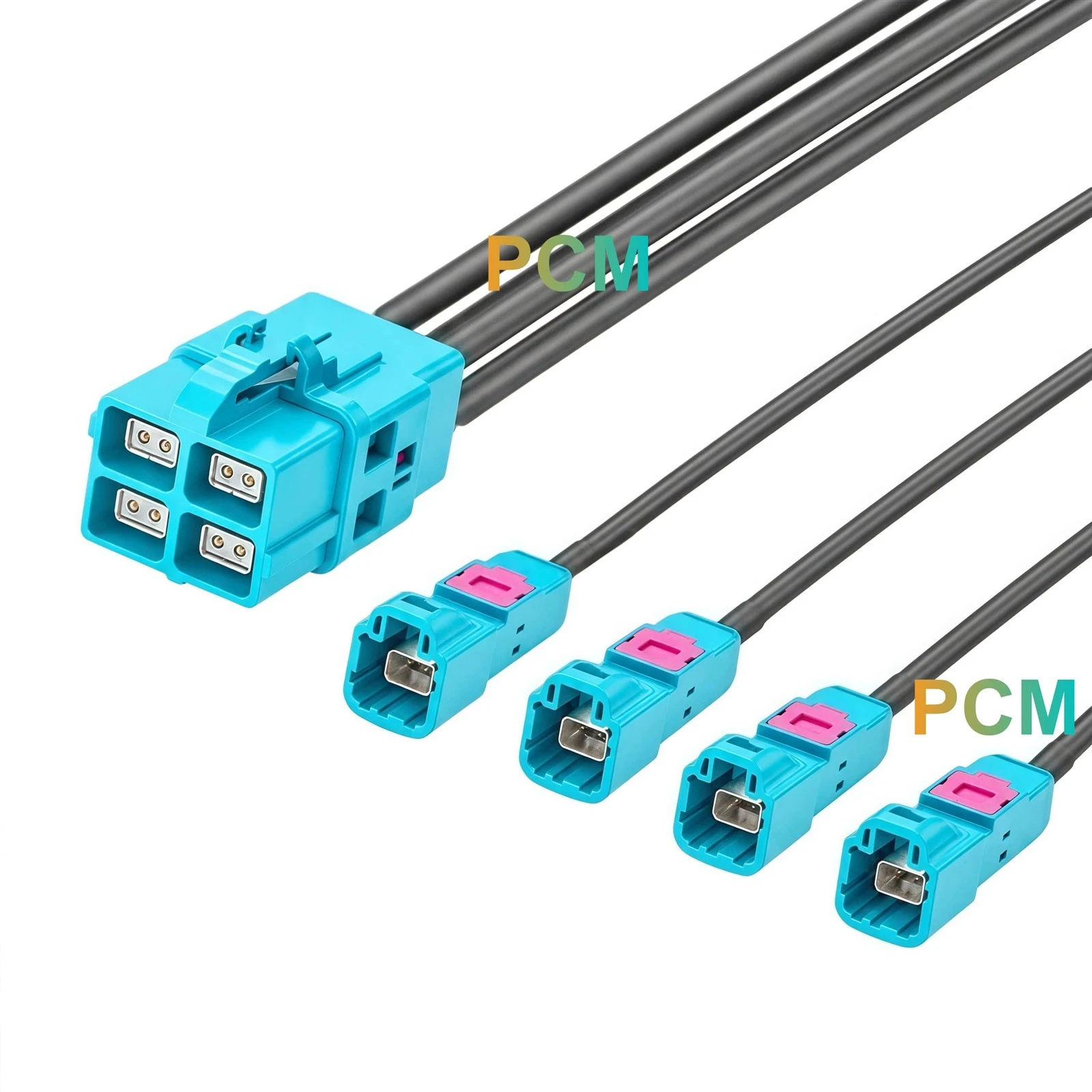
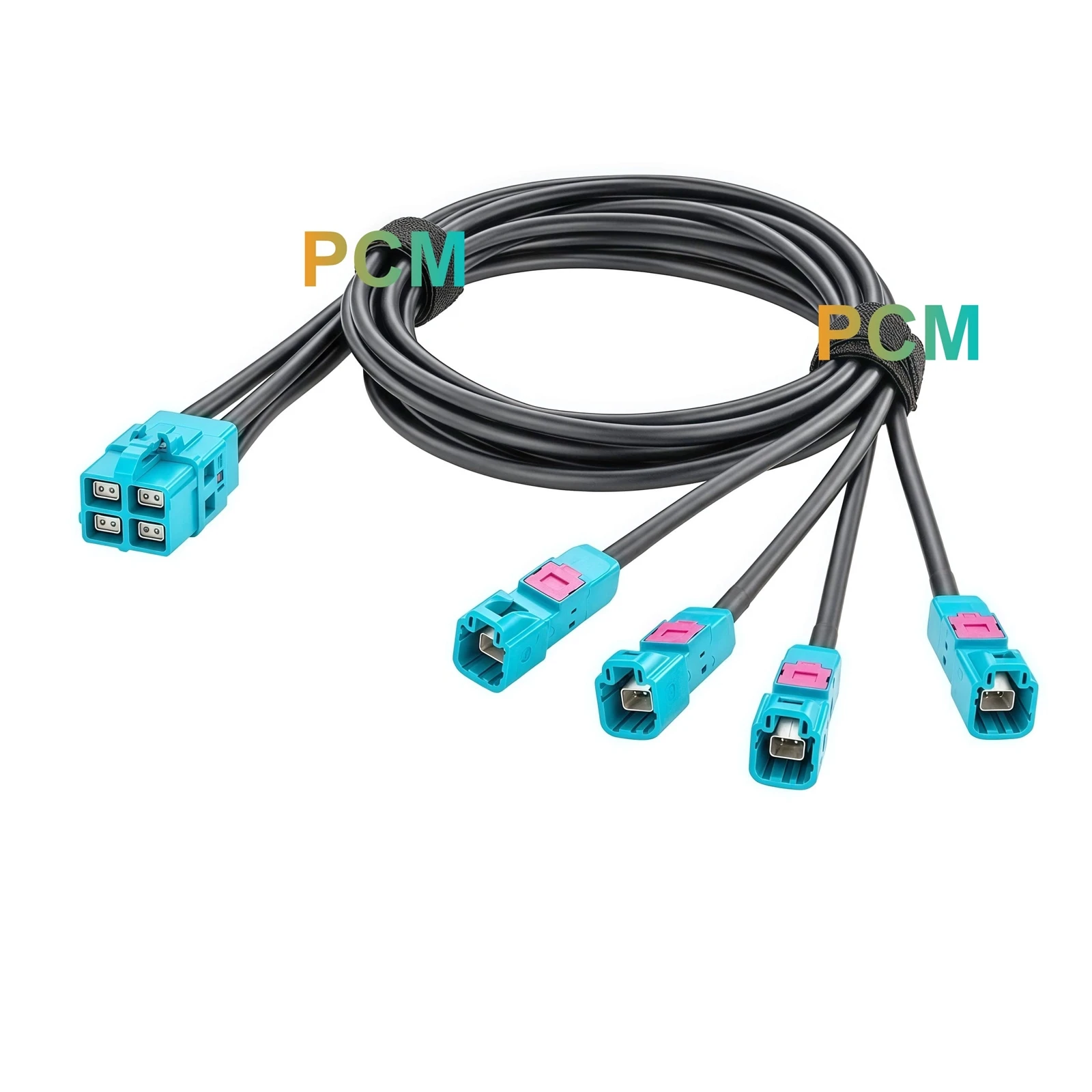
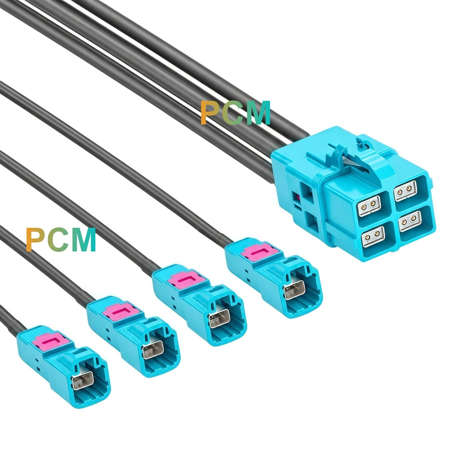
The main connector holds four female contact interfaces in a square arrangement beneath a shared top latch. Each two contact interface occupies its own projecting front section, while the rear body brings the four cable entries together. This structure establishes one grouped mating location at the equipment end, so access around the common housing and latch can be planned as a single installation requirement.
Four Plugs With Independent Mating Access
The remote ends use four individually housed ECT 818026772 plugs, each with a recessed metal interface and a visible pink component on top. Their separate bodies allow each plug to approach its mating position independently. Unlike a rigid four port block, the branch ends do not impose a fixed spacing between remote connections, leaving their placement to the approved harness route and equipment geometry.
Direct Cable Runs Without a Junction Body
Four individual cables leave the back of the main housing and continue directly to their respective plugs. No external junction body sits between the grouped connector and the branch ends. The harness therefore separates through cable routing rather than through an additional splitter enclosure, allowing installation planning to focus on cable support, branch separation and clearance at the five connector positions.
Applications & Customer Value
Connections to Distributed Jacks
Four male ends connect to separately located mating jacks, with each connector interface checked against the specified mating connector model.
Sequential Fixture Setup
Operators can connect the remote ends one at a time as fixture components are installed, while keeping a grouped connection at the main end.
Equipment Assembly Routing
Separate cable runs can follow different mounting positions within the equipment, without requiring an intermediate junction box along the route.
Branch Level Troubleshooting
An accessible remote plug can be disconnected for individual circuit checks, without unplugging the other remote ends during troubleshooting.
Product Features
ECT 818026772 Z Code Plug Ends
All four individual cable branches use the same specified male connector type, establishing consistent remote mating interface requirements across the entire harness assembly.
Assigned Contact Pair Routing
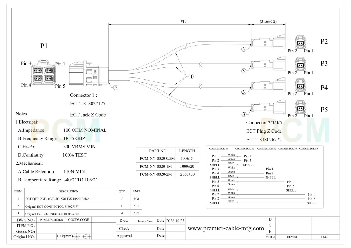
P1 pins 1 and 2 connect to P2, pins 3 and 4 to P3, pins 5 and 6 to P4, and pins 7 and 8 to P5. This defines four separate circuits rather than a parallel signal split.
Corresponding Shell Ground Connections
The drawing includes a dedicated shell ground path for each individual branch, establishing the required termination arrangement alongside the signal conductors.
Specified ECT Cable and Assembly Checks
The bill of materials identifies QFP12GD100-B-5G cable. Continuity, dielectric withstand and cable retention requirements establish inspection points for the completed harness.
Customization Capabilities
Premier Cable supports the following customization options:
Connector Customization
Select connector type, gender, coding and housing design to match the mating interface, port layout and equipment connection requirements.
Cable Customization
Customize overall length, branch lengths, jacket material, shielding and cable structure to suit routing space and installation requirements.
Electrical Customization
Confirm pin assignment, wiring and circuit configuration, with resistance values and power ratings reviewed against project requirements.
OEM Manufacturing
Support drawing review, prototype builds and mass production, with custom branch labels and packaging to match project assembly requirements.
Product FAQ
Q1. Is this a four port network switch?
No. The supplied drawing defines a wired interconnect without switching electronics or network management functions.
Q2. When should male branch ends be selected instead of female ends?
Select the branch gender from the confirmed remote mating connector. Similar appearance or matching coding does not replace a mating part check.
Q3. Can it connect directly to a specific controller or development board?
That requires confirmation of the board connector model, mating geometry, contact assignment and electrical interface. No specific controller compatibility is established by the supplied drawing.
Q4. How should the required harness length be specified?
Use the drawing's L reference and provide the actual routing dimensions. Confirm whether the project requires equal or different branch lengths before releasing the production drawing.
Q5. What should be approved before an OEM production order?
Approve the connector list, dimensions, pin assignment, ground connections, branch identification and inspection criteria against the sample or released drawing.

Hot Tags: ect z code 4 plug breakout cable, China ect z code 4 plug breakout cable manufacturers, suppliers, factory