
Product Specifications
| Item | Specification |
| Number of Contacts | 4 |
| Characteristic Impedance | 90Ω |
| Cable Outer Diameter | 4.6mm |
| Connector Brand | Hirose |
| Axial Pull Strength | ≥110 N |
| Frequency Range | 480 MHz |
| Cable Length | 600±20mm |
| P1 Connector | USB2.0 A/F |
| Insulation Resistance | 100 MΩ Min |
| Insertion and Extraction Durability | ≥25 cycles |
| Drawing Number | PCM-ZC-0255 |
| P2 Connector | GT17H-4S-2C |
| P2 Connector Shell | GT17HS-4S-HU |
| Operating Temperature | -40 to 105°C |
| Withstand Voltage | 500 V RMS Min |
| Insulation Material | Transparent PE material |
| Outer Jacket | 45P PVC compound, black |
| Cable Construction | USB2.0 (26#/1P+AM)+24#/2C+AB OD4.6MM |
| Product Type | USB 2.0 Type A Female to Hirose GT17H Cable Assembly |
Product Design and Functional Features
USB Socket for Equipment Interface Extension
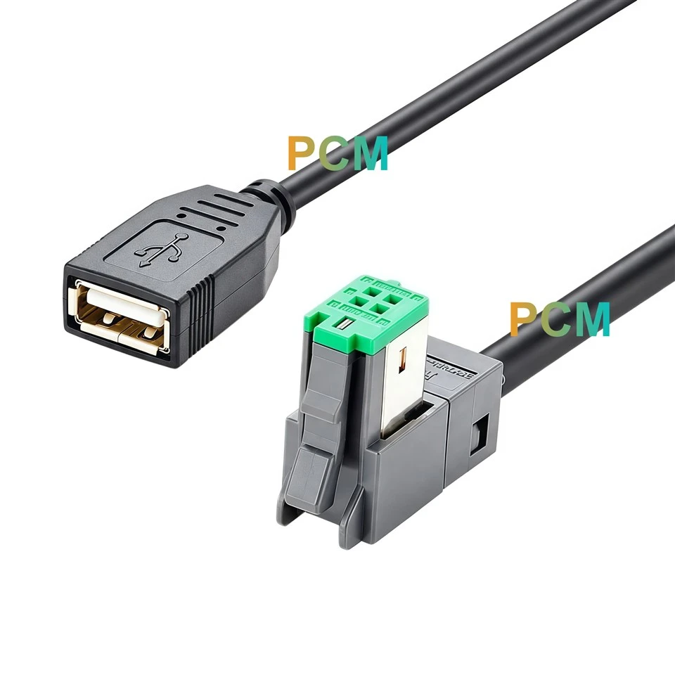
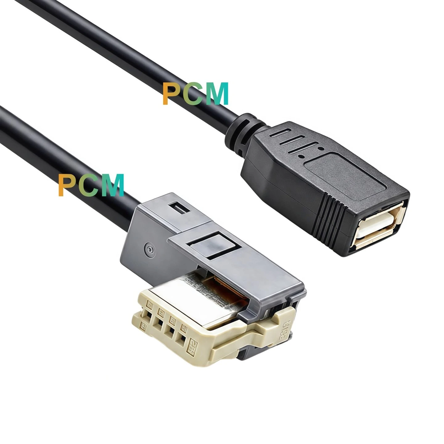
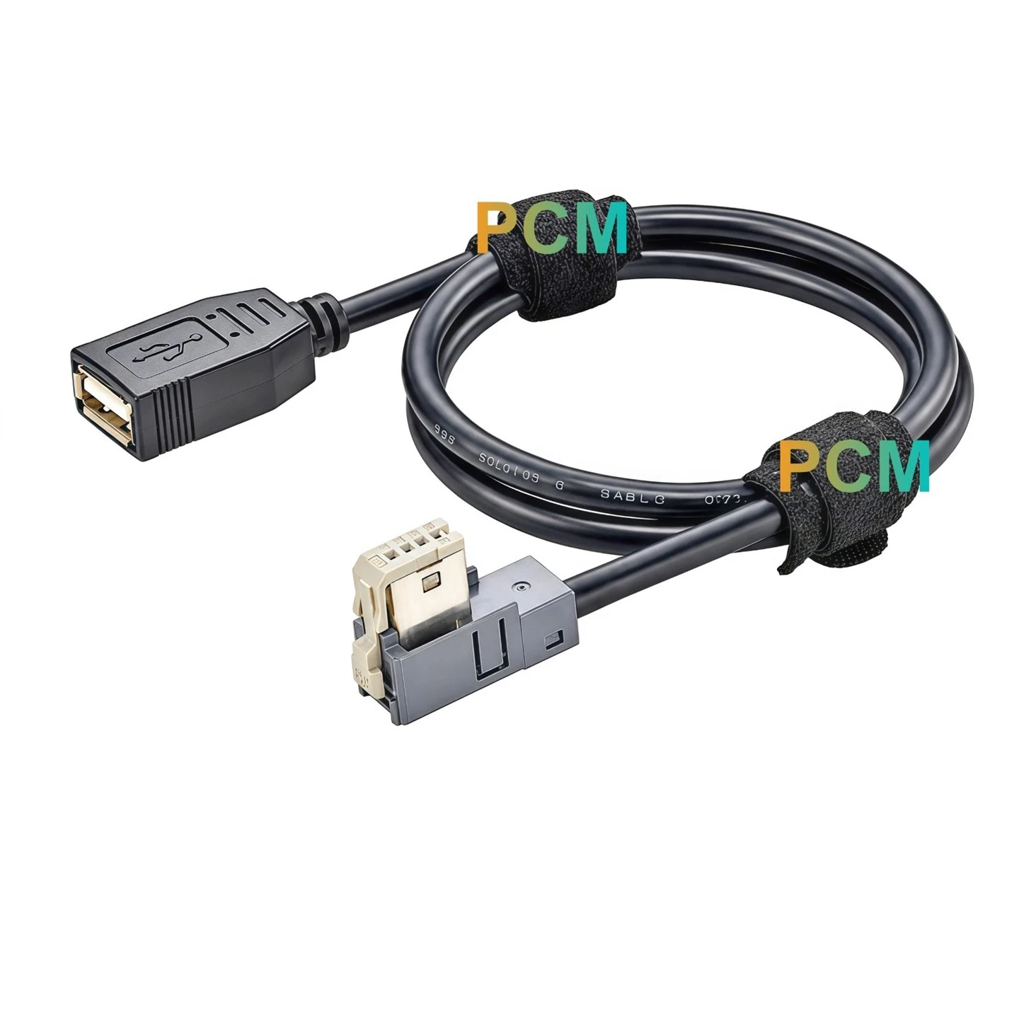
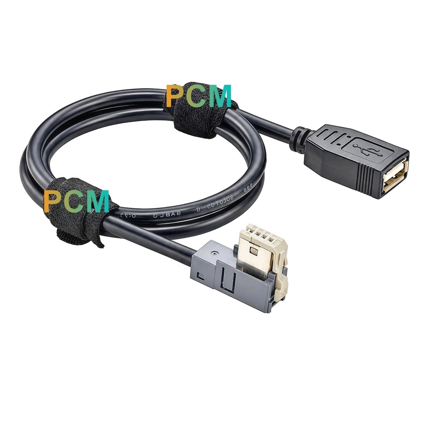
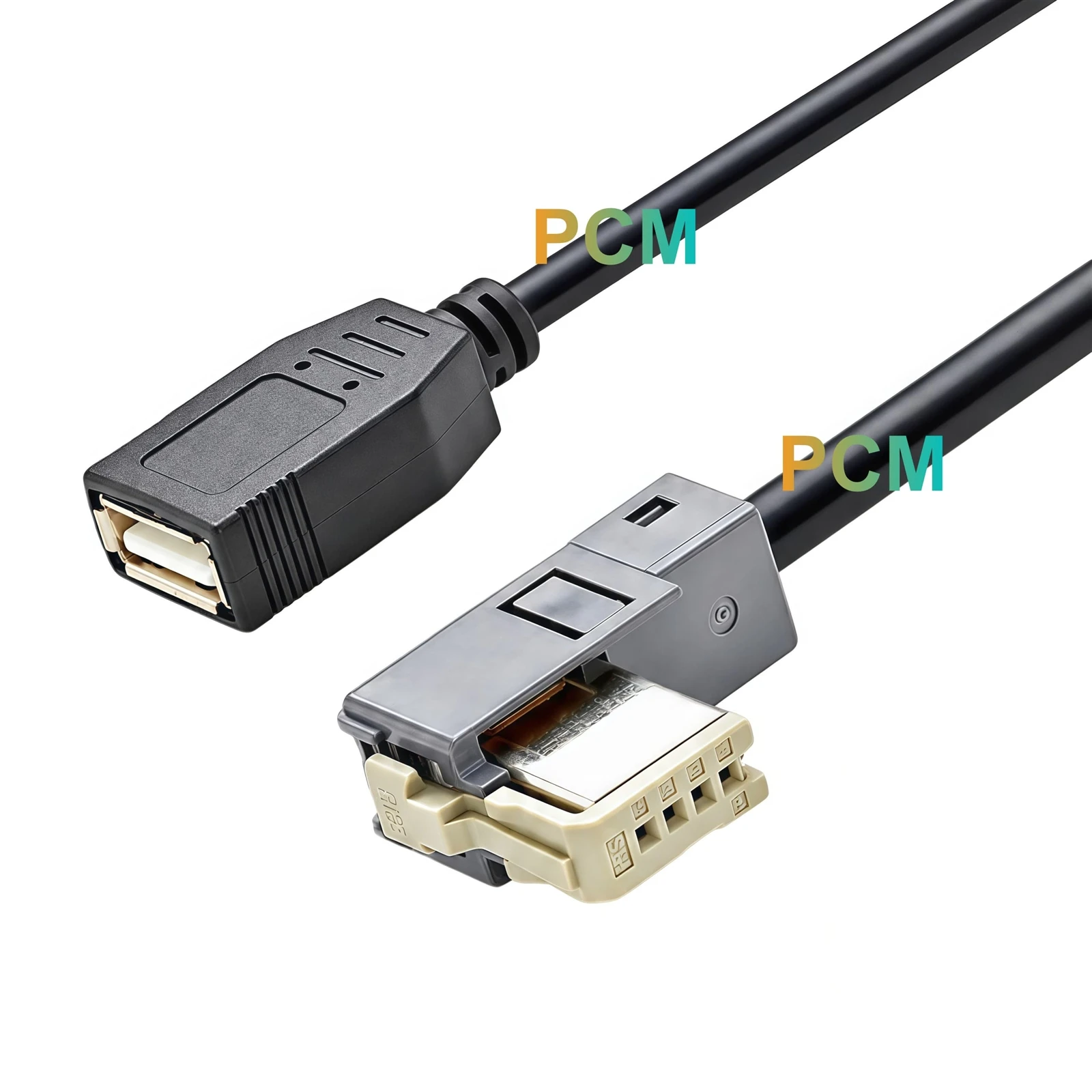
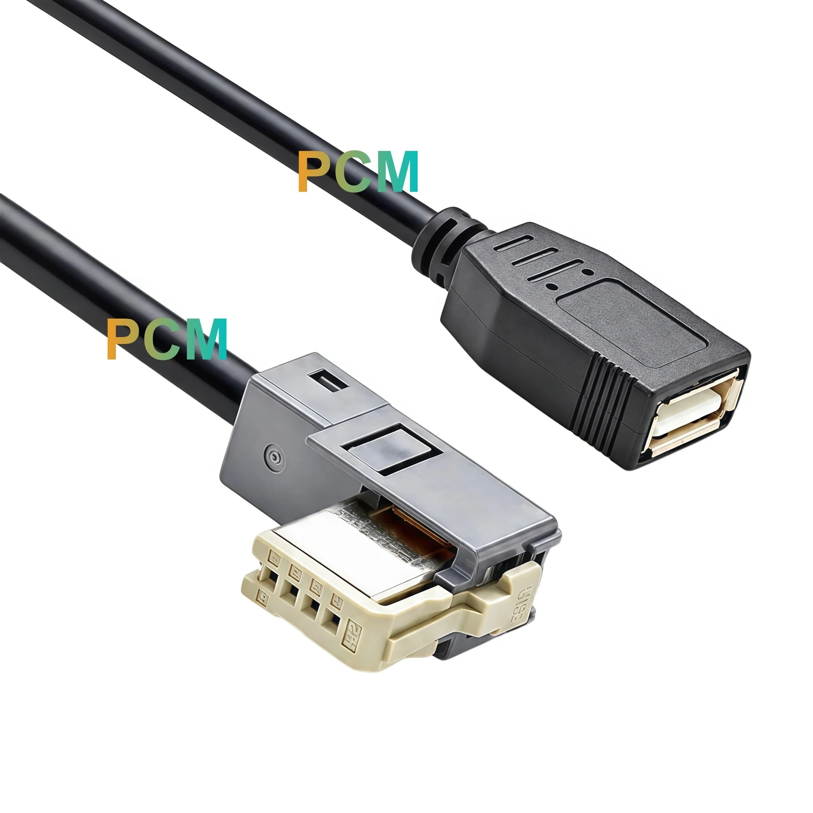
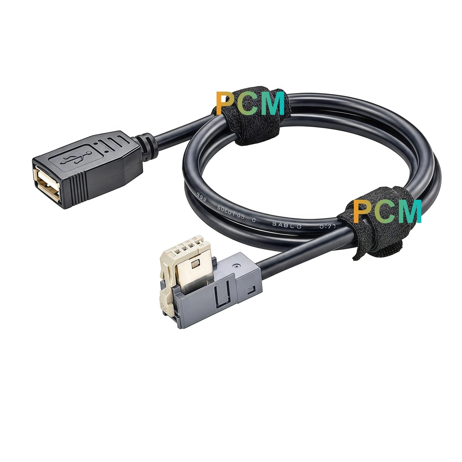
The P1 end features a USB 2.0 Type A Female socket housed in a molded black enclosure. Rather than terminating in a conventional USB plug, this configuration provides a receptacle for an external USB connection. It allows equipment designers to position the USB access point away from the main electronic assembly while retaining a wired connection to the dedicated GT17H interface. This arrangement is useful for equipment layouts where the USB connection needs to be accessible at a separate location.
Original Hirose GT17H Connector Configuration
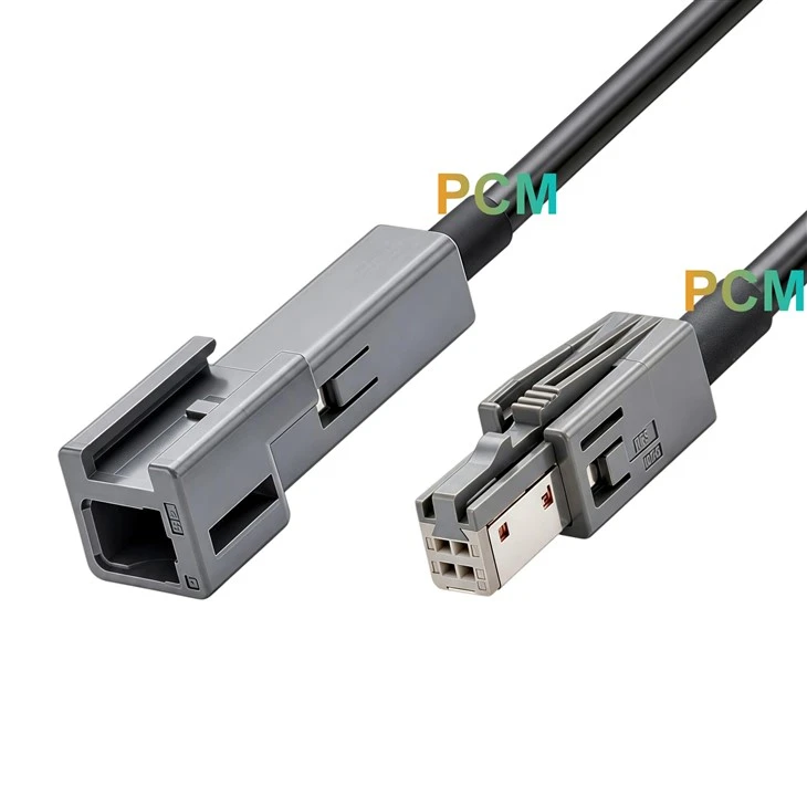
At P2, the assembly uses the Hirose GT17H-4S-2C connector together with the GT17HS-4S-HU shell. The four position connector configuration provides the specified mating interface for compatible equipment. The light colored connector insert and gray outer housing are visible features of the assembly. Retaining the original manufacturer part numbers provides a clear reference for component identification, sourcing and production inspection, particularly in projects where the equipment interface is already defined by a specific GT17H connector configuration.
Four Pin Signal Assignment
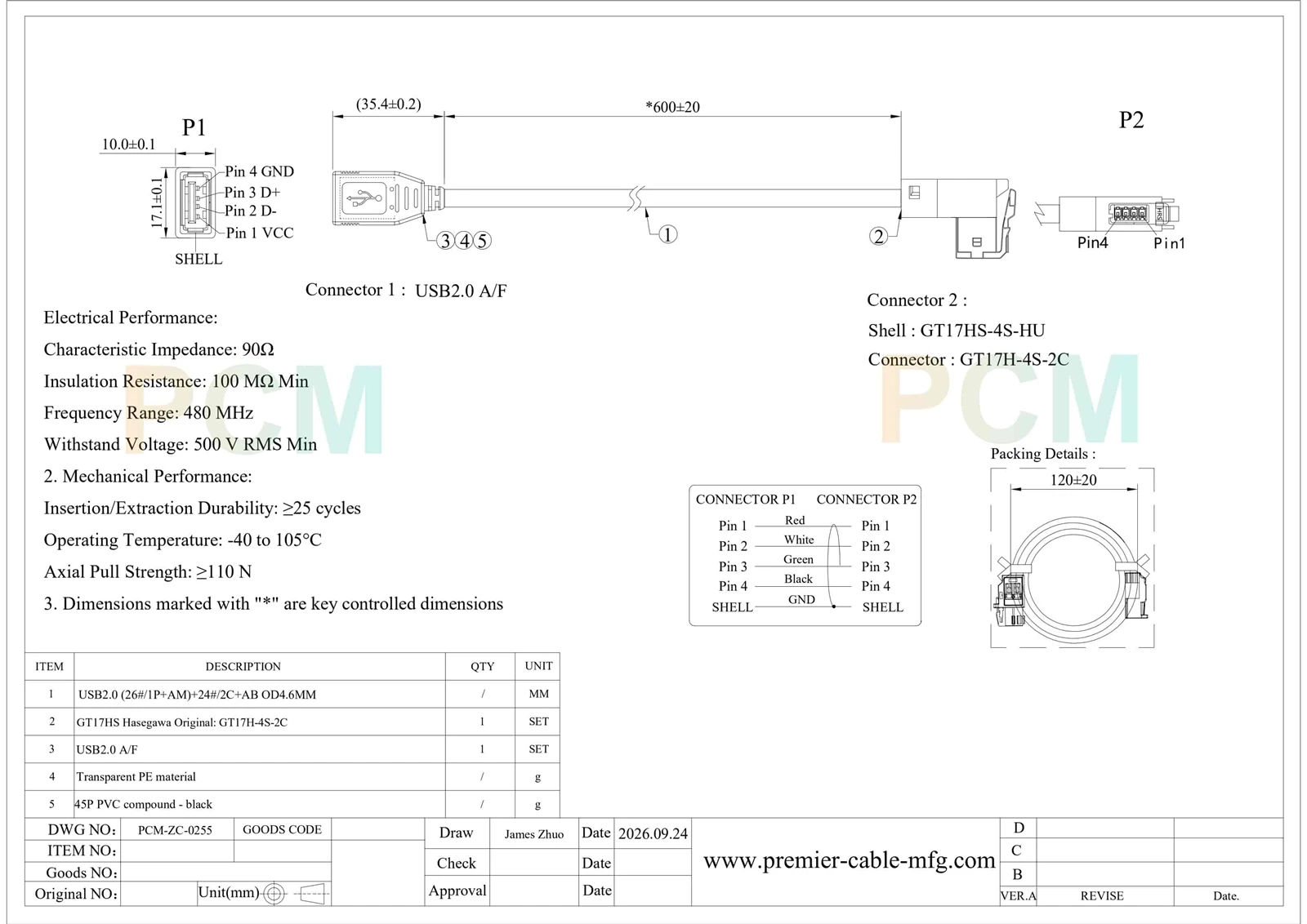
The cable follows the pin assignment shown in the engineering drawing. Pin 1 carries VCC, Pin 2 carries D-, Pin 3 carries D+, and Pin 4 carries GND. The corresponding wire colors are red, white, green and black. Both connector shells are connected to GND according to the drawing. This defined arrangement provides an identifiable reference for electrical continuity checks and wiring verification during cable assembly production. It also helps equipment manufacturers maintain the required signal correspondence when integrating the cable into an existing USB interface design.
Controlled Cable Dimensions and Material Structure
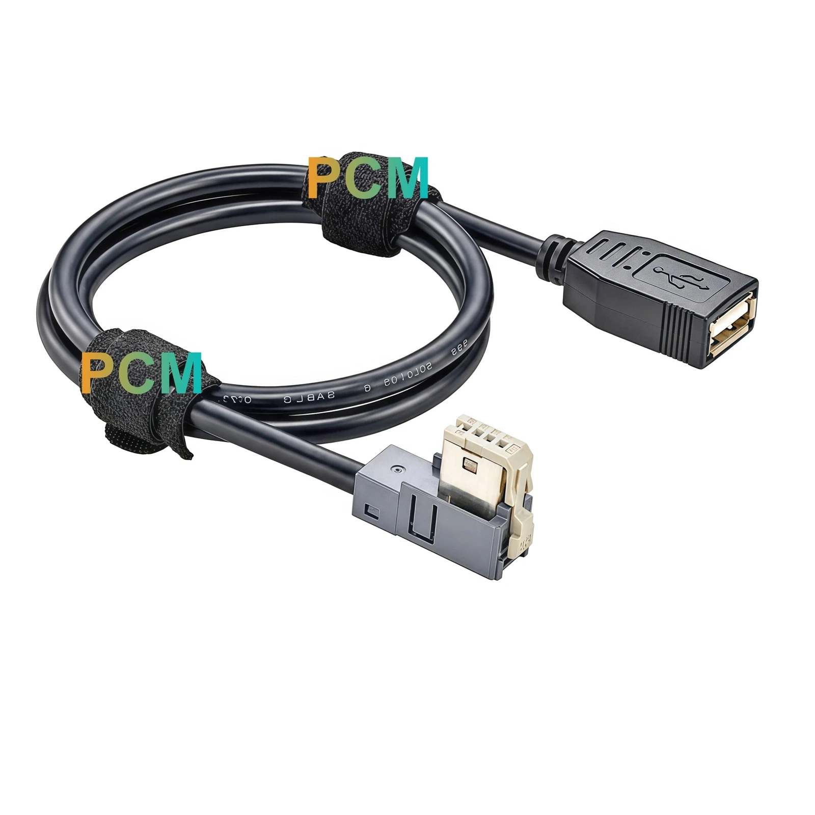
The assembly has a specified finished cable length of 600±20mm and an outer cable diameter of 4.6mm. Its construction follows the drawing designation USB2.0 (26#/1P+AM)+24#/2C+AB OD4.6MM. Transparent PE material is specified for the internal insulation, while the outer jacket uses black 45P PVC compound. These construction details establish the material and dimensional references for manufacturing. The defined cable length also provides a practical connection span between the USB socket and the equipment side connector.
Equipment Applications and Customization
USB Access Point Integration
This assembly can be incorporated into electronic equipment that requires a remotely positioned USB socket. The USB 2.0 Type A Female interface provides an accessible connection point, while the cable routes the signals to the equipment side GT17H connector. This arrangement is suitable for embedded electronic units and automotive equipment with dedicated internal USB connections.
GT17H Interface Compatibility
The Hirose GT17H-4S-2C connector and GT17HS-4S-HU shell establish the equipment side connection specified in the drawing. This makes the assembly relevant to projects using the corresponding GT17H interface and four pin signal assignment. The original connector identification also simplifies component matching when developing replacement cables or integrating new equipment.
Drawing Based Cable Development
Premier Cable supports cable assembly development based on customer drawings and defined component requirements. Cable length, connector selection, pin assignment, insulation materials and jacket specifications can be evaluated for different equipment layouts. Prototype samples and production arrangements can be coordinated according to the electrical and mechanical requirements of each project.
Product Drawing
Product FAQ
How are the four USB signals assigned ?
The wiring follows the drawing: red for VCC, white for D-, green for D+, and black for GND. These correspond to Pin 1, Pin 2, Pin 3 and Pin 4 respectively. Both connector shells are connected to GND.
What is the connector configuration of PCM-ZC-0255 ?
PCM-ZC-0255 uses a USB 2.0 Type A Female socket at P1 and an original Hirose GT17H-4S-2C connector with GT17HS-4S-HU shell at P2. The equipment side connection follows a four pin configuration.
What is the specified cable length ?
The finished cable length is 600±20mm, measured according to the engineering drawing. The cable outer diameter is 4.6mm, providing a defined dimensional reference for equipment installation and cable routing.
What electrical performance requirements are specified ?
The drawing specifies 90Ω characteristic impedance, 100 MΩ minimum insulation resistance, a 480 MHz frequency range and 500 V RMS minimum withstand voltage. The specified operating temperature is -40 to 105°C.
Can this GT17H cable assembly be customized ?
Yes. Premier Cable can evaluate alternative cable lengths, connector configurations, wire assignments and material requirements according to customer engineering drawings. Prototype development and production planning can be discussed for specific equipment integration projects.

Hot Tags: hirose gt17h-4s-2c to usb 2.0 cable, China hirose gt17h-4s-2c to usb 2.0 cable manufacturers, suppliers, factory