

Product Specifications
| Parameter | Specification |
| Characteristic impedance | 90Ω |
| Cable outer diameter | 4.6mm |
| Frequency specified in drawing | 480MHz |
| PCM drawing number | PCM-ZC-0252 |
| Axial pull strength | 110N minimum |
| Insulation resistance | 100MΩ minimum |
| Operating temperature | −40°C to 105°C |
| Dielectric withstand voltage | 500V RMS minimum |
| Insertion and extraction durability | 25 cycles minimum |
| Connector configuration | Hirose GT17H A Key at both ends |
| Contact layout | Four positions in one row at each end |
| Cable exit sleeve | Black, 5.0mm outer diameter and 20mm long |
| Shell at each end | Hirose GT17HS-4S-HU, dark gray outer housing |
| Controlled cable length | 2000mm ± 20mm between drawing reference points |
| Connector insert at each end | Original Hirose GT17H-4S-2C(A), brown A Key insulation case |
| Cable construction | Shielded USB 2.0 cable with one 26 AWG pair and two 24 AWG conductors |
The Single Row GT17H Connection

Four Contacts in One Line
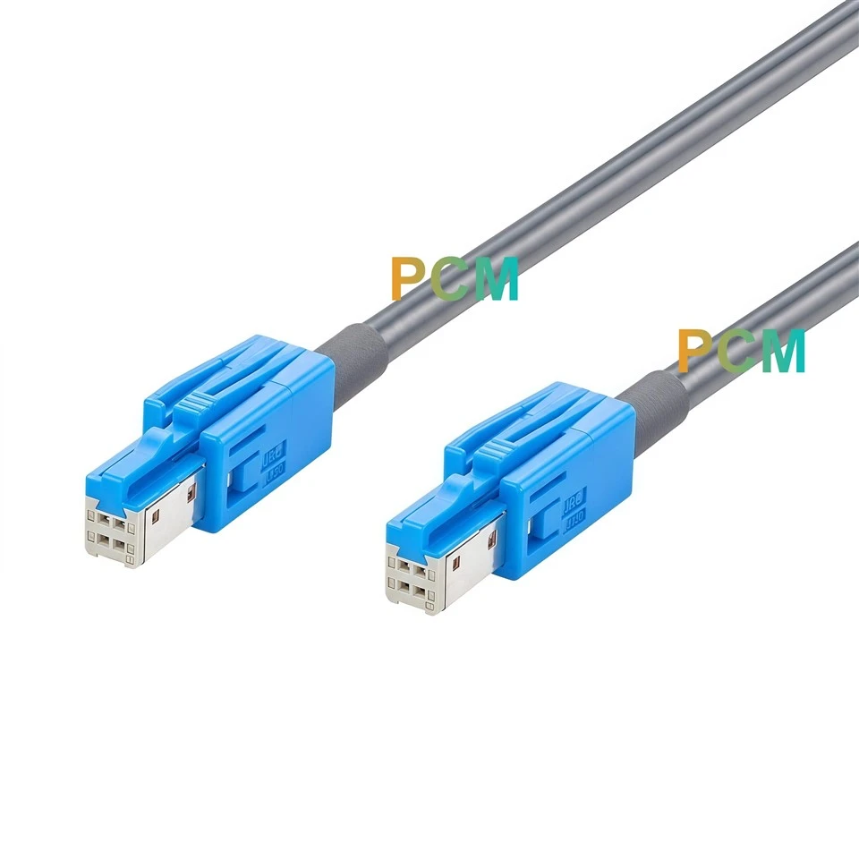
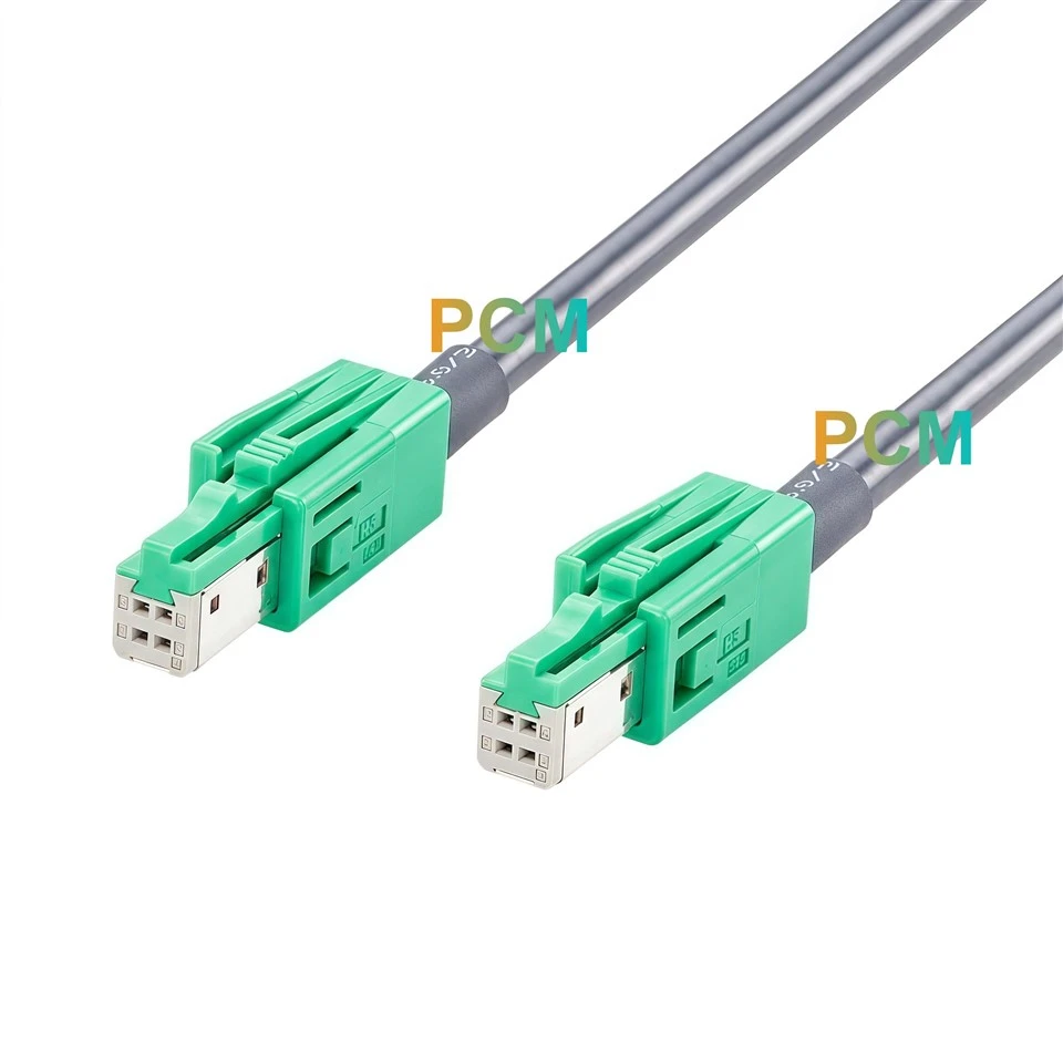
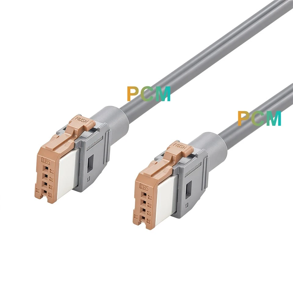
The mating face is the quickest way to identify this cable. All four contacts sit in a single row, with the position numbers visible on the brown insert. If the equipment drawing lists only four positions and A Key, ask for the mating part number or a face view before ordering. A photo taken from the cable side can hide the contact layout entirely. For sample approval, compare both connector faces with the equipment drawing and use the numbered positions to orient the sample before checking continuity.
The Brown Insert Carries the A Key
The brown GT17H-4S-2C(A) insert defines the mating key. It sits inside the dark gray GT17HS-4S-HU housing, which the PCM drawing lists as Shell. That distinction matters when a purchasing list includes the gray housing number but leaves out the insert. Specify both numbers to identify the finished cable end. For receiving inspection, look at the brown mating face and confirm the insert number against the purchase specification, especially when several GT17H variants share the same outer housing.


USB Cable Construction With a Documented Pin Map
The shielded cable contains one 26 AWG pair and two 24 AWG conductors, with a characteristic impedance of 90Ω. The assembly drawing identifies the four paths by pin number and wire color. It also shows a separate connection between the metal shells. When using the cable in an automotive USB link, compare both module pin tables before applying power. The red, white, green and black wire colors make the conductors easier to trace during inspection. The equipment documentation defines the signal and power assignments.
Plan for the Release Tab and Cable Exit
The brown release tab is marked PUSH. Check that it remains accessible once the module is mounted, particularly when a trim panel or fixture bracket sits above the connector. At the rear, the 20mm sleeve takes up space before the cable can turn toward its first clip. Measure the proposed route using the 2000mm ± 20mm span shown on the drawing, then check the space needed to withdraw each connector. On a bench fixture, this lets technicians swap modules without pulling on the cable.

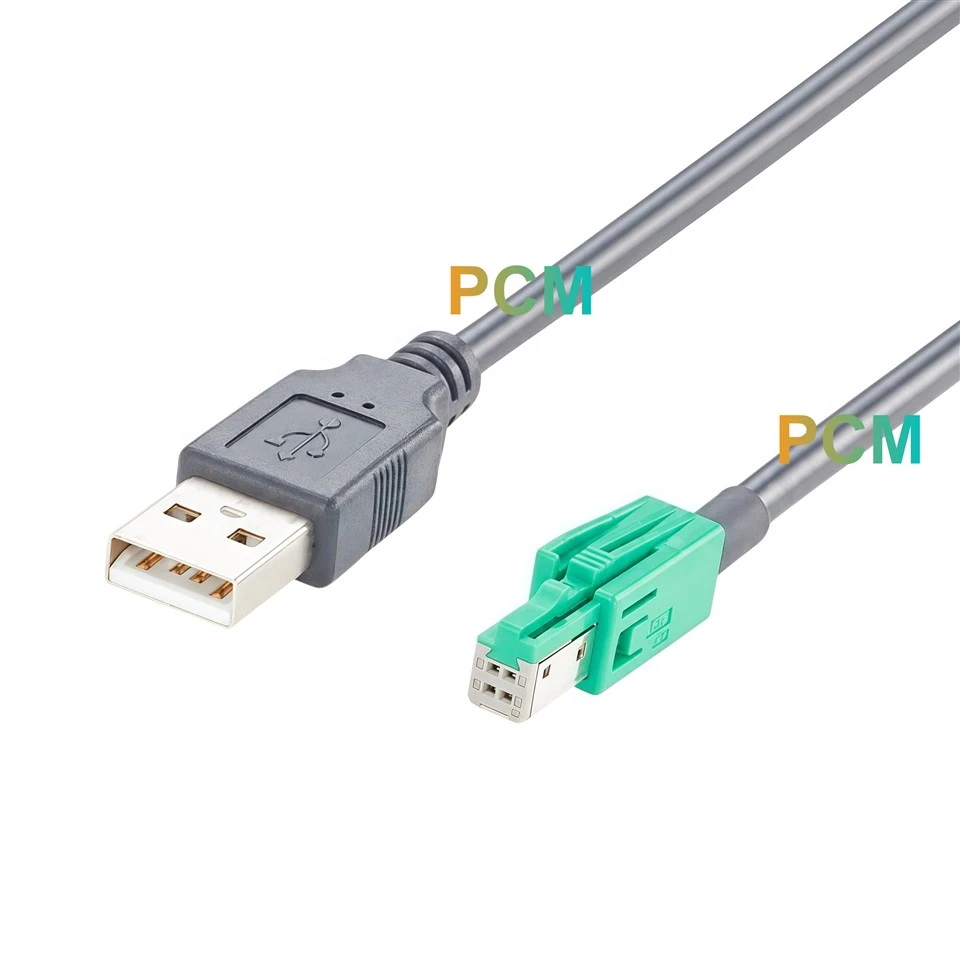
Where the USB Female End Fits
Infotainment module development
Link a head unit and a compatible media module when both use mating Hirose GT17H A Key ports with matching USB assignments.
Console packaging trials
Check the cable route behind the trim and verify that the release tabs remain accessible with the surrounding hardware installed.
Module validation fixtures
Use the same single row connector and pin map planned for the prototype while checking communication between modules mounted apart on the bench.
Product Drawing

Product FAQ
Will this cable fit a Hirose GT32 A Key port ?
PCM-ZC-0252 uses the Hirose GT17H single row interface. For a Hirose GT32 A Key port, check the GT32 mating part number and select the corresponding cable assembly.
Which part number identifies the brown A Key insert ?
GT17H-4S-2C(A) identifies the brown A Key insulation case. GT17HS-4S-HU identifies the dark gray outer housing. hirose.com
Can I plug either end into either module ?
Yes, when both modules have mating Hirose GT17H A Key ports and their signal assignments match the straight through pin map. Both cable ends have the same connector configuration.
Does 480MHz specify the USB data rate ?
480MHz is the frequency value listed on the assembly drawing. Confirm USB compatibility and supported data rates using the requirements of the complete module link.
What should I send PCM for a quote ?
For the configuration shown, send drawing number PCM-ZC-0252 and your estimated quantity. If you need a different length or wiring layout, include the mating part number at each end and the required pin map.

Hot Tags: hirose gt17h a key to a key 4 pin cable, China hirose gt17h a key to a key 4 pin cable manufacturers, suppliers, factory