

Product Specifications
| Parameter | Specification |
| Characteristic impedance | 90Ω |
| Cable outer diameter | 4.6mm |
| Frequency specified in drawing | 480MHz |
| Controlled cable length | 2000±20mm |
| PCM drawing number | PCM-ZC-0259 |
| Axial pull strength | 110N minimum |
| Insulation resistance | 100MΩ minimum |
| Operating temperature per drawing | −40°C to 105°C |
| Dielectric withstand voltage | 500V RMS minimum |
| Mating durability | 25 cycles minimum |
| Connector reference dimension | 31.25±0.15mm at each end |
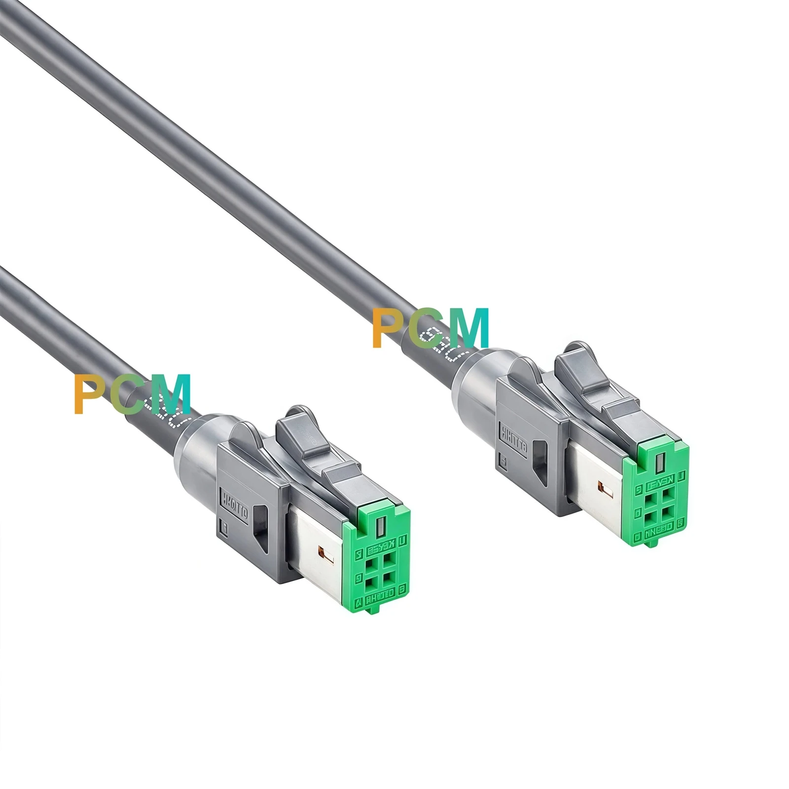
| End configuration | Hirose GT17HN B Key at both ends |
| Contact layout | Four positions in two rows at each end |
| Shell at each end | GT17HNS-4DS-HU, dark gray outer housing |
| Connector at each end | GT17HN-4DS-2C(B), green B Key insulation case |
| Cable exit sleeve | Black, 5.0mm outer diameter and 20mm long at each end |
| Cable construction | Shielded USB 2.0 cable with one 26AWG pair and two 24AWG conductors |
What to Check on a Bench With Multiple GT17HN Variants

Look at Both Faces Before Fitting the Lead
The dark gray housings can look alike when several GT17HN leads are stored together. Turn both ends toward you and check the green B Key face and its two rows of contacts. The GT17HN-4DS-2C(B) connector identifies the keyed insert, while GT17HNS-4DS-HU identifies the outer shell. For a station that handles different module variants, put PCM-ZC-0259 on the setup sheet and record the insert number in the fixture parts list. This gives operators a visual check at the bench and gives buyers an exact reference when reordering.
Keep the Lead in Place During Module Swaps
Both ends have the same mating profile and wiring, so the fixture can use either cable end at either module when the ports and signal assignments match. If one module is replaced more often, route the lead so its latch is easy to reach and leave enough slack to withdraw the connector by its housing. The 2000±20mm dimension applies between the marked points on the drawing. Account for both connector bodies and the 20mm sleeves when deciding where the first clips should sit.

Check the Cable Before Investigating the Modules
If two compatible modules stop communicating after a swap, the pin map gives technicians a quick way to check the cable. Pin 1 runs to pin 1, and the same pattern applies through pin 4. Check the four numbered paths individually, then check continuity between the metal shells. If those paths match the drawing, compare the pin assignments on the two module revisions. A shared B Key interface confirms the mating profile, while the module documentation determines which signal belongs on each contact.
Separate the Cable Specification From the System Test
The cable uses a shielded construction with one 26AWG pair, two 24AWG conductors and a characteristic impedance of 90Ω. Keep those details with the connector part numbers when reviewing a replacement lead or requesting a different length. On the bench, check device recognition and communication with the actual host and device modules connected. The drawing's 480MHz value is a frequency specification. Use the complete module setup to verify the USB data rate required by the project.

Automotive Integration and Test Applications
Shared benches for multiple module variants
Assign the green B Key lead to the corresponding fixture setup so operators can identify it before installing a module.
Console and dashboard mockups
Check the routed span between module locations and confirm that both connectors can be released after brackets and trim are fitted.
Head unit and media module testing
Connect two modules with mating GT17HN B Key ports and matching USB assignments to check device recognition and communication.
Product Drawing

Product FAQ
Is the Hirose GT17HN B Key connector fitted at both ends ?
Yes. Both cable ends use the same green GT17HN-4DS-2C(B) connector, securely fitted inside a dark gray GT17HNS-4DS-HU outer shell.
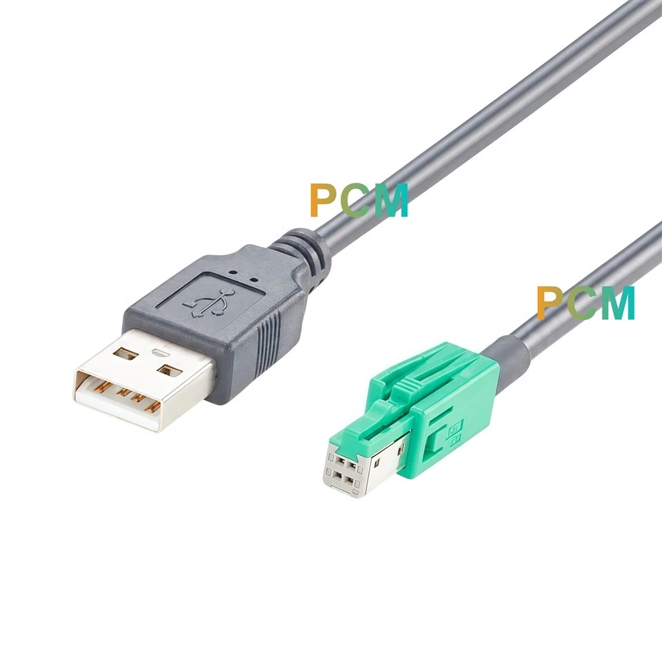
Does the USB 2.0 cable construction mean there is a USB Type A plug ?
Both cable ends terminate in matching Hirose GT17HN B Key connectors. USB 2.0 describes the cable construction as specified on the drawing.
What should I include in a sample request ?
Reference PCM-ZC-0259 and include estimated quantity. For variations, provide each mating connector part number, target length, and required pin map.
How do I measure the cable for a fixture ?
Measure the proposed route against the 2000±20mm span between drawing reference points. Check connector bodies, release tabs and sleeved exits separately for clearance.
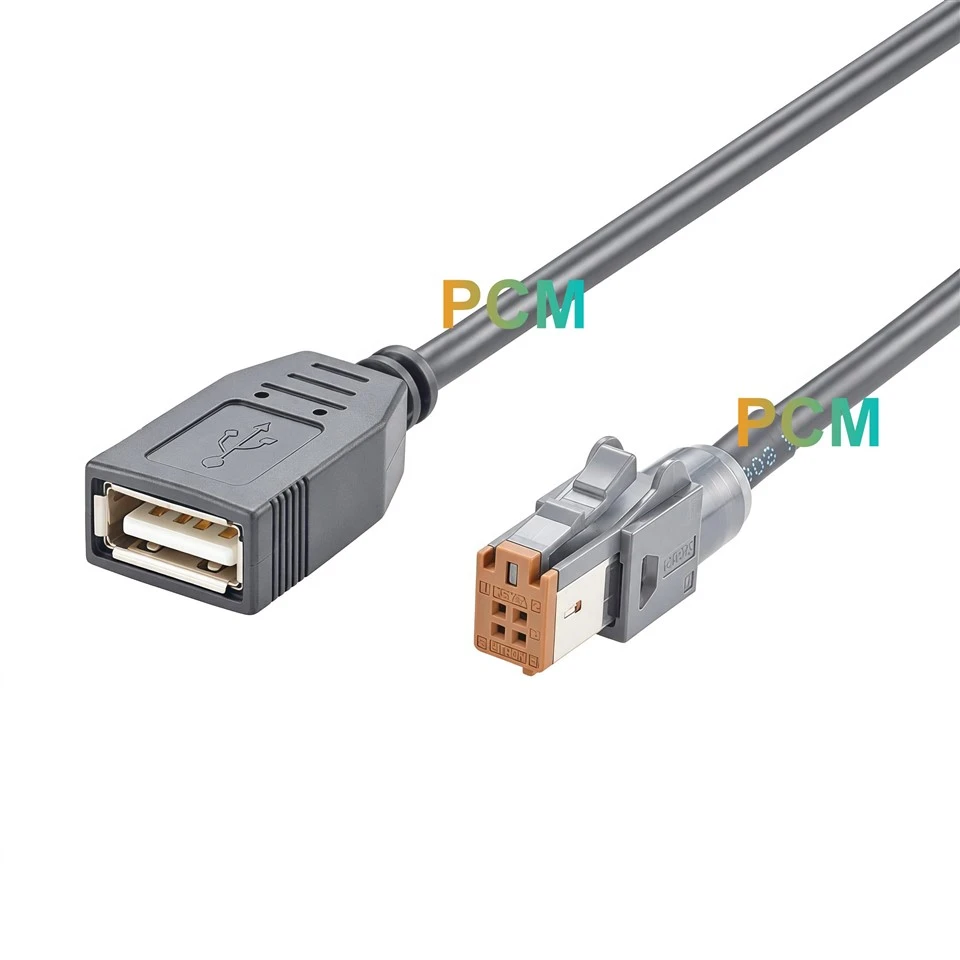
Can I use this cable if one module has a brown A Key port ?
The two ports must mate with the green GT17HN B Key ends on this assembly. If one module uses A Key, include the mating part number for each module when requesting a different configuration.

Hot Tags: hirose gt17hn dual row b key to b key cable, China hirose gt17hn dual row b key to b key cable manufacturers, suppliers, factory