
Product Specifications
| Parameter | Details |
|---|---|
| Common Connector Brand | ECT |
| Common Connector Reference | 818018736 |
| Common Housing Color | Bordeaux |
| Common Connector Construction | Sealed |
| SMA Connector Quantity | Four |
| Version 1 SMA Reference | SMA-J2-3 |
| Version 1 SMA Gender | Male |
| Version 2 SMA Reference | SMA-KY-2 |
| Version 2 SMA Gender | Female |
| Custom Options | Cable Length |
| Connector Orientation | Straight at Both Ends |
| Coding | ECT Mini FAKRA D Code |
| Common Connector Type | Mini FAKRA Four Cavity Female |
| Product Type | Four Channel RF Coaxial Cable Assembly |
| Version 2 SMA Mounting | Bulkhead Panel Mount with Nuts and Washers |
| Listed Cable Options | RTK031 Coaxial Cable, Including DACAR302-4 and ECT302LL |
Available Configurations

ECT Mini FAKRA D Code to Four SMA Male Cable
Connection Structure
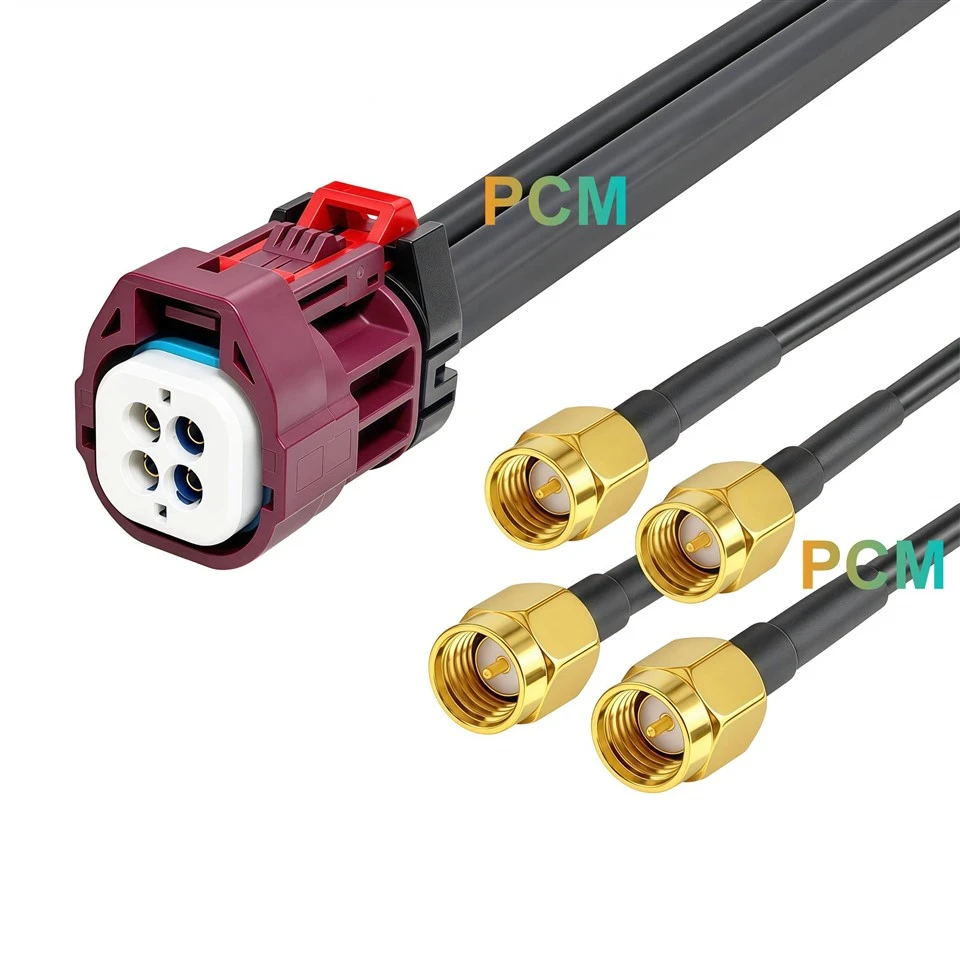
One 818018736 ECT Mini FAKRA D Code four cavity female connector connects to four SMA-J2-3 straight male connectors.
Unique Difference
Each SMA end has a center pin and an internally threaded coupling nut, allowing each branch to connect directly to an SMA female port.
Suitable Installation
Evaluation boards, instruments or equipment with accessible SMA female interfaces where panel mounting is unnecessary.
ECT Mini FAKRA D Code to Four SMA Bulkhead Female Cable
Connection Structure
One 818018736 ECT Mini FAKRA D Code four cavity female connector connects to four SMA-KY-2 straight bulkhead female connectors.
Unique Difference
Externally threaded connector bodies, nuts and washers allow the four SMA connection points to be secured individually to a panel.
Suitable Installation
Test boxes and equipment enclosures requiring external SMA access. Mounting hole dimensions and panel thickness should follow the connector drawing.

Applications & Customer Value
Camera Hardware Evaluation
Camera development may require access to individual coaxial paths while retaining the device's grouped connector. Separate connection points allow engineers to arrange the supporting equipment around the required measurement or evaluation setup.
Test Fixture Construction
A fixture needs connection points that operators can locate and reach consistently. Defined port positions and identification reduce uncertainty during repeated cable changes and test preparation.
Equipment Enclosure Integration
Internal wiring should accommodate both the device location and external cable access. A harness planned around the enclosure layout allows the connection points to be positioned without placing the main equipment connector at the panel surface.
Service Connection Planning
Development equipment may be disconnected frequently for replacement or inspection. Accessible connection locations and a documented channel map support servicing without repeatedly handling the grouped device interface.
Product Features
D Code Mating Geometry
The common connector uses D Code mechanical keying. Its Bordeaux housing provides visual identification, while the mating profile determines the required equipment interface.
Four Position Contact Insert
A white internal insert accurately locates four coaxial connection positions inside the common housing. Each position continues through its own individual cable branch to an SMA termination.
Clearly Visible Housing Locking Mechanism
The ECT connector includes a contrasting red locking component above the housing. Its exposed position allows the assembly to be visually checked before installation.
SMA Termination Hardware
The male version uses coupling nuts for cable mating. The female version adds panel retention hardware, separating connector mounting from the attachment of an external SMA cable.
Customization Capabilities
Premier Cable supports:
Connector Customization
Premier Cable reviews connector type, gender, coding and housing design against the specified mating interfaces. Alternative SMA mounting styles or branch combinations can be evaluated for the equipment layout.
Cable Customization
Overall length and individual branch dimensions can be defined from the installation drawing. Jacket material, shielding and cable structure are reviewed together with connector attachment and sealing requirements.
Electrical Customization
Pin assignment, cavity mapping and wiring definitions can be documented for the intended equipment. Requests involving circuit configuration, resistance values or power ratings require engineering assessment before production.
OEM Manufacturing
Premier Cable supports drawing review, prototype preparation and mass production following specification approval. Branch labels, product identification and packaging can be arranged for installation control and repeat purchasing.
Product FAQ
Q1. Is this cable a four way RF signal splitter ?
No. It carries four separate coaxial paths. No circuit is specified for dividing one input signal into multiple outputs.
Q2. Are the SMA connectors standard polarity or reverse polarity ?
The supplied images show standard SMA construction: center pins on the male ends and center sockets on the female ends. They are not identified as RP-SMA connectors.
Q3. Can this D Code harness replace a C Code assembly ?
Replacement requires confirmation against the device's mating interface. The same cavity count and SMA branch arrangement do not establish coding compatibility.
Q4. Does the sealed ECT end establish an IP67 Waterproof rating for the complete harness ?
No. The supplied information does not confirm a complete assembly rating or a protection rating for the SMA ends. Environmental requirements must be assessed for the finished installation.
Q5. What is needed for an OEM sample quotation ?
Provide the selected version, mating references, cavity to branch map, cable requirements and dimensions. For the bulkhead version, include the panel layout, mounting requirements and required label text.

Hot Tags: ect mini fakra to sma cable, China ect mini fakra to sma cable manufacturers, suppliers, factory