

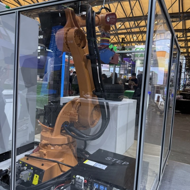
Vision Guided Robotics (VGR) is a technology that integrates machine vision systems with industrial robots, enabling robots to "see" and make real-time decisions based on visual information. The core principles are:
- Perception: The camera (2D/3D) captures images/point clouds of the work scene.
- Processing: Vision software (such as OpenCV, Halcon, Cognex VisionPro) analyzes the image to locate the target object, detect defects or measure dimensions.
- Guidance: The processing results (such as object coordinates and posture) are sent to the robot controller through the communication interface.
- Execution: The robot dynamically adjusts the path to complete tasks such as grasping, assembly, and welding.
Core advantages
- High adaptability: handle randomly placed objects (such as scattered workpieces).
- High precision: exceeds the absolute positioning accuracy of the robot (up to ±0.05mm).
- Flexibility: quickly switch production tasks and reduce hardware adjustments.
Key components and common connectors/cables
The following are the hardware and interfaces involved in the VGR system:
| Component | Common Connectors and Cables | Function Description |
|---|---|---|
| Industrial Camera | M8/M12 Circular Connectors (threaded locking, vibration-resistant) | Provides power (5/12/24V) and data transfer. Common for IP67-rated cameras. |
| GigE Vision: RJ45 jack (Cat5e/Cat6 cable) | Gigabit Ethernet transfer, supports PoE (Power over Ethernet). Max distance ≤100m. | |
| USB3 Vision: USB Type-B port (shielded USB cable) | High-speed transfer (5Gbps). Max distance ≤5m. Requires EMI protection. | |
| Camera Link: MDR26 port | High bandwidth (up to 6.8Gbps). Max distance ≤10m. Requires frame grabber. | |
| CoaXPress: BNC connector (coaxial cable) | Single-cable power + data (CXP-12: 12.5Gbps). Max distance ≤40m. | |
| Lens | C/CS Mount (standard industrial interface) | Compatible with most industrial cameras. |
| Light Controller | LEMO/M12 Connectors (4–6 pins) | Powers pulsed LED lighting and synchronizes with external triggers. |
| Robot Controller | EtherNet/IP: RJ45 jack (industrial-grade cable) | Mainstream protocol (e.g., FANUC, KUKA) for transmitting vision coordinates. |
| Profinet: RJ45 jack (shielded) | Common in Siemens ecosystems. | |
| RS-232/RS-485: DB9 port (serial cable) | Legacy systems or simple command transfer. | |
| I/O Module | M12 Connectors (A/B-coded, 4–8 pins) | Transmits trigger signals, E-stop commands (e.g., camera trigger → robot start). |
| Vision Processor/Industrial PC | PCIe Interface (Camera Link/CoaXPress frame grabber) | Dedicated image capture cards installed in PCIe slots. |

Selection considerations
1. Environmental adaptability:
- For factory environments, choose M12/M8 waterproof connectors (anti-oil, anti-vibration).
- For long-distance transmission, fiber conversion (such as GigE to fiber) is preferred.
2. Bandwidth matching:
- High-resolution cameras (such as 12MP) require interfaces above GigE Vision/Camera Link.
3. Synchronization accuracy:
- Use hardware trigger lines (such as I/O cables) to ensure microsecond synchronization of camera-robot-light source.
4. Electromagnetic compatibility:
- Choose shielded twisted pair (such as Cat6 SF/UTP) and keep away from power cables.
Typical application scenarios
- Random picking (Bin Picking): 3D camera guides the robot to grab disordered workpieces.
- High-precision assembly: Visual compensation for part position deviation (such as mobile phone parts fitting).
- Quality inspection: Online detection of product defects and sorting.


