M8 Sensor Cable Pinout Guide: 3-Pin vs 4-Pin and How to Choose
A practical guide to typical M8 3-pin and 4-pin sensor wiring, A-coded connectors, cable compatibility and the key details to check before selecting an M8 sensor or actuator cable.
Quick reference: A 3-pin M8 sensor cable commonly carries supply voltage, 0 V and one signal. A 4-pin cable adds another contact that can be used for an additional or device-specific function. The extra pin does not automatically make a 4-pin cable compatible with a 3-pin device.
Important wiring note: The pin assignments shown in this guide are typical arrangements used in many industrial sensor applications. Always verify the connected sensor, actuator or I/O device wiring diagram before ordering or replacing a cable.
Contents
1. M8 3-Pin vs 4-Pin: What Is the Difference?
M8 connectors are widely used to connect compact industrial sensors, actuators and field devices. Two cables may look almost identical while using different numbers of contacts and different internal wiring.
The basic difference is simple: a 3-pin M8 cable provides three electrical contacts, while a 4-pin cable provides a fourth contact that can support an additional signal or another function defined by the connected equipment.
| Feature | M8 3-Pin | M8 4-Pin |
|---|---|---|
| Number of Contacts | 3 | 4 |
| Typical Application | Basic three-wire sensors | Sensors or devices requiring an additional contact |
| Supply Connection | Yes | Yes |
| Typical Signal Capacity | One primary signal | Primary signal plus possible additional function |
| Automatically Interchangeable? | No | No |
Key point: Choose the cable according to the connected equipment specification. More contacts do not automatically mean better performance or broader compatibility.
2. How M8 Sensor Cable Wiring Works

Power and Signal in One Compact Connection
An M8 sensor cable normally carries the electrical supply and sensor signals between a field device and an I/O module, PLC interface or other control equipment.
A-coded M8 connectors are commonly associated with sensor and actuator applications. The same physical connector family can be supplied with different pin counts, male or female contacts, straight or right-angle cable exits and different termination styles.
When reading a pinout drawing, always check the viewing direction. A diagram showing the mating face can appear different from a drawing viewed from the cable or wiring side.
Do not identify wiring by connector appearance alone: Two M8 connectors can have the same size and contact count while being wired for different equipment functions.
3. Typical M8 3-Pin Sensor Cable Pinout
Three-pin M8 cables are commonly found on relatively simple three-wire industrial sensors. A typical arrangement uses one contact for positive supply, one for 0 V and one for the switching or sensor signal.
| Pin | Typical Wire Color | Typical Function |
|---|---|---|
| Pin 1 | Brown | Positive supply |
| Pin 3 | Blue | 0 V / supply return |
| Pin 4 | Black | Sensor signal / switching output |
Proximity Sensors
Common in machine presence and position detection applications.
Photoelectric Sensors
Used for object detection in packaging, handling and automation equipment.
Switching Sensors
Suitable where the device needs supply plus a single switching signal.
This is a common arrangement rather than a universal rule. The equipment datasheet should remain the final reference for voltage, signal function and pin assignment.
4. Typical M8 4-Pin Sensor Cable Pinout
A four-pin M8 cable adds one additional contact. Depending on the connected sensor, actuator or I/O device, that contact may be used for a second output, an additional input or another equipment-specific function.
| Pin | Typical Wire Color | Typical Function |
|---|---|---|
| Pin 1 | Brown | Positive supply |
| Pin 2 | White | Additional / device-specific signal |
| Pin 3 | Blue | 0 V / supply return |
| Pin 4 | Black | Main signal / device-defined function |
What the fourth pin means: It provides another available electrical contact. It does not automatically mean higher power, higher performance or direct compatibility with every 4-pin M8 device.
5. Can You Use a 4-Pin M8 Cable with a 3-Pin Sensor?
Sometimes the connectors may mate physically, but electrical compatibility should never be assumed.
A replacement cable must match the equipment electrically as well as mechanically. Before substituting one cable for another, check the following:
Confirm that the mechanical coding matches the device interface.
Check the connector gender required at each end of the cable.
Compare every active contact with the device wiring diagram.
Verify voltage, current and signal requirements for the connected equipment.
Compatibility rule: Matching connector size and pin count alone do not confirm that two M8 cables are electrically interchangeable.
6. Common M8 Cable Configurations
Pin count is only one part of cable selection. M8 assemblies are available in several physical configurations depending on the sensor, machine layout and control system.
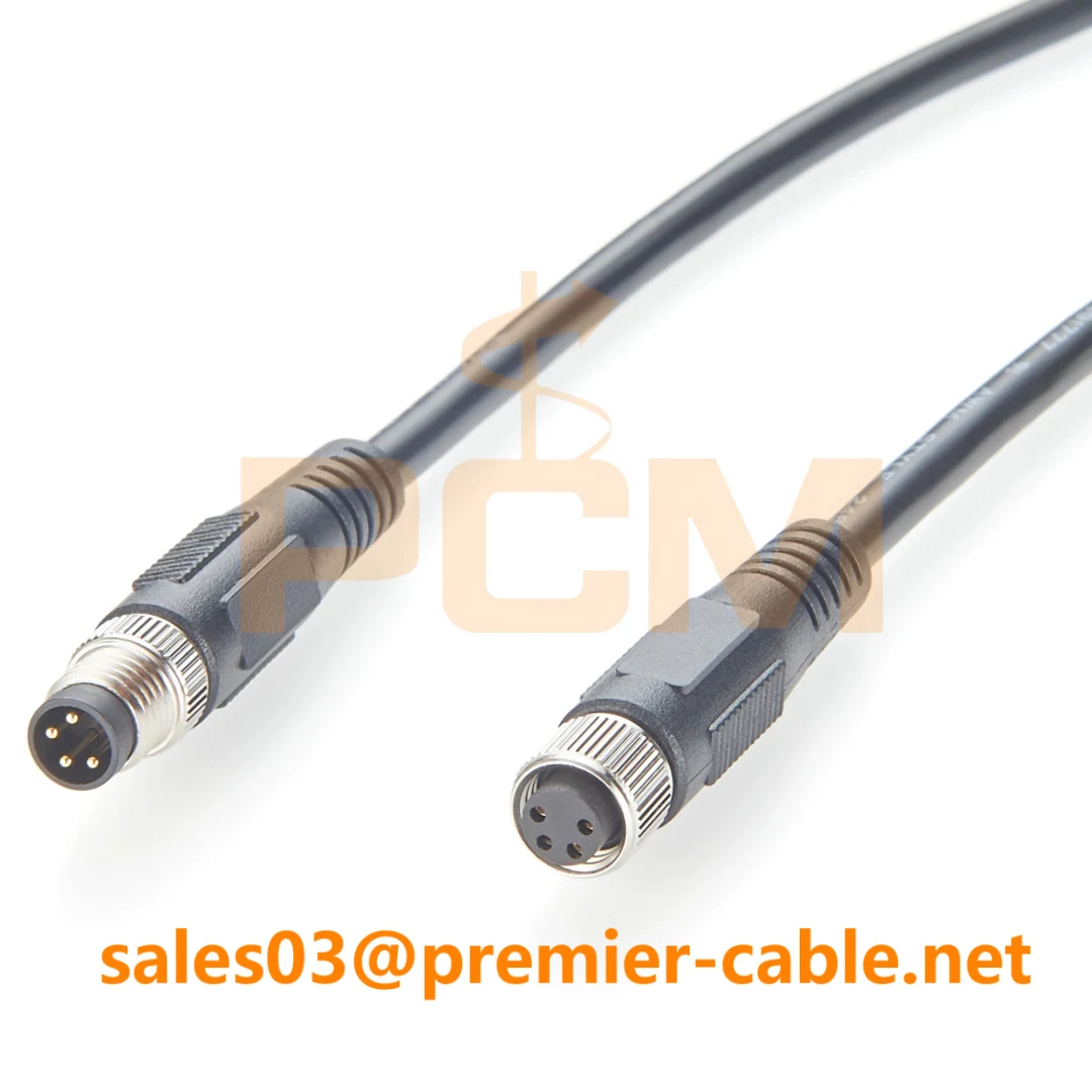
M8 Male-to-Female Sensor & Actuator Cable
Male-to-female M8 cables are widely used as extension assemblies between sensors, actuators and machine wiring. They allow additional routing distance without modifying the original device connection.
When selecting an extension cable, confirm the number of contacts, pin-to-pin wiring, connector coding and required length. Straight and right-angle versions can also help accommodate different machine layouts.
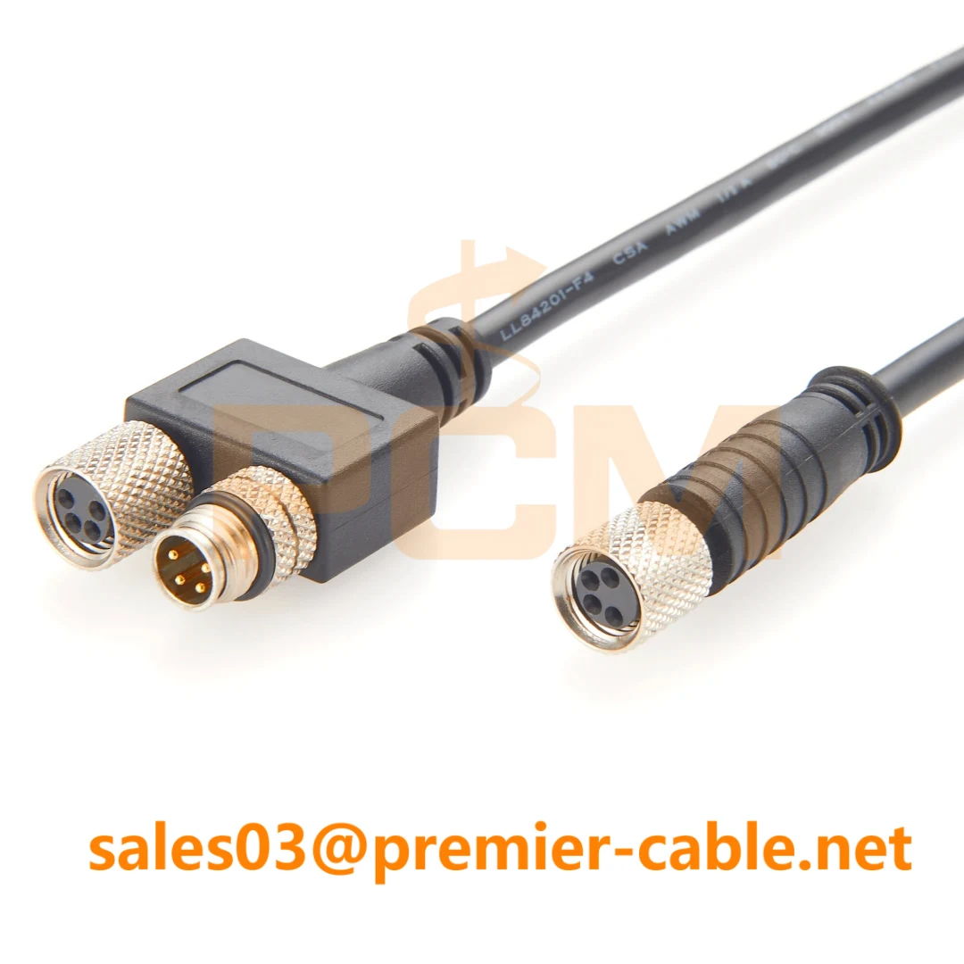
M8 Splitter Cables
Y-type and other M8 splitter assemblies are used where a machine wiring design requires multiple branch connections from a compact harness.
A splitter should not be treated as a universal way to duplicate every sensor signal. The wiring arrangement, connected load and equipment design must support the intended branch configuration.
Other M8 configurations can include open-wire leads, panel-mount cables, bulkhead assemblies and interface cables for equipment-specific applications.
M8 does not always mean sensor wiring: M8 connectors can also appear in industrial communication and equipment interface applications. Sensor/actuator cables and industrial network cables may use different coding and pin assignments.
7. How to Choose the Right M8 Sensor Cable
The easiest way to select an M8 sensor cable is to start with the connected device rather than searching only by connector appearance.
| Check | What to Confirm | Why It Matters |
|---|---|---|
| Pin Count | 3-pin, 4-pin or other configuration | Determines available electrical contacts |
| Coding | Confirm equipment connector coding | Prevents mechanical and application mismatch |
| Gender | Male, female or open-wire termination | Must match the mating interface |
| Pinout | Function of every active contact | Confirms electrical compatibility |
| Cable Style | Straight, right-angle, extension, splitter or panel mount | Fits the physical installation |
| Cable Construction | Length, jacket, shielding and environment | Matches routing and operating conditions |
A Simple Example
If you need to replace a 4-pin M8 sensor extension, finding another cable labeled only as "M8 4-pin" is not enough. The connector coding, male/female arrangement, pin assignment and cable length should all match the original application.
8. Custom M8 Sensor and Actuator Cable Assemblies
Standard M8 cables cover many industrial automation applications, but OEM equipment, replacement projects and machine integration may require a different cable length, pin assignment or connector format.
Connector Configuration
- M8 male or female
- 3-pin or 4-pin configurations
- Straight or right-angle
- Panel-mount or bulkhead
- Open-wire termination
Cable Requirements
- Custom overall length
- PVC or PUR jacket options
- Shielded or unshielded construction
- Specific wire gauge
- Application-specific cable routing
Project Requirements
- Custom pin assignment
- Y or splitter configuration
- Connector and cable labeling
- Equipment-specific replacement cable
- Drawing or sample-based production
Recommended information for custom M8 cable projects: provide the equipment model, connector configuration, pin count, pinout, required cable length and quantity. A drawing, wiring diagram, existing cable photo or physical sample can also help confirm the required assembly.
Frequently Asked Questions
What is the difference between an M8 3-pin and 4-pin sensor cable?
A 4-pin M8 connector provides one additional electrical contact. The extra contact can be used for an additional signal or another device-defined function, depending on the equipment.
Can I use a 4-pin M8 cable with a 3-pin sensor?
Not automatically. Even when the connectors can physically mate, the coding and electrical pin assignment must match the sensor specification.
Are all M8 4-pin cables wired the same?
No. An M8 connector format can be used with different equipment and pin assignments. Confirm the actual wiring instead of selecting a replacement only by the number of contacts.
Is an M8 sensor cable the same as an M8 Ethernet cable?
No. Sensor and actuator connections and industrial network interfaces can use different coding, wiring and electrical requirements even when both products use an M8 connector format.
Can M8 sensor cables be customized?
Yes. Connector gender, pin count, pin assignment, cable length, jacket, shielding, orientation, termination style and labeling can be specified according to the application.
Need Help Selecting an M8 Cable?
Send the equipment model, M8 connector configuration, pin count, pinout, required cable length and quantity. Premier Cable can review the connection requirement and recommend a suitable sensor, actuator, extension, splitter, panel-mount or custom M8 cable assembly.
Custom connector configurations, cable lengths, pin assignments, jackets, shielding and labeling can be discussed for industrial automation, robotics, sensor and OEM equipment applications.