

Product Specifications
| Item | Specification |
| Pin Count | 4 |
| Characteristic Impedance | 90Ω |
| Casing Length | 20mm |
| Keying Type | A Key |
| Cable Outer Diameter | 4.6mm |
| Axial Pull Strength | ≥110N |
| Casing Outer Diameter | 5.0mm |
| Connector Brand | Hirose |
| Signal Type | USB2.0 |
| Frequency Range | 480MHz |
| P1 Orientation | Straight |
| Contact Arrangement | Dual Row |
| Cable Length | 2000±20mm |
| Insulation Resistance | 100MΩ Min |
| Insertion and Extraction Durability | ≥25 Cycles |
| Premier Cable P/N | PCM-ZC-0243 |
| P2 Orientation | Right Angle |
| Withstand Voltage | 500VRMS Min |
| P2 Housing | GT17HN-4DS-HU |
| P1 Housing | GT17HNS-4DS-HU |
| Operating Temperature | -40°C to 105°C |
| P1 Connector | GT17HN-4DS-2C(A) |
| P2 Connector | GT17HN-4DS-2C(A) |
| Pin Assignment | VCC, D-, D+, GND |
| Protective Casing | Single Wall Casing |
| Cable Construction | USB2.0 (26#/1P+AM)+24#/2C+AB |
| Product Type | Hirose GT17HN to GT17HN Cable Assembly |
Dual Connector Configuration and Mechanical Design
Same Connector Model, Different Housing References
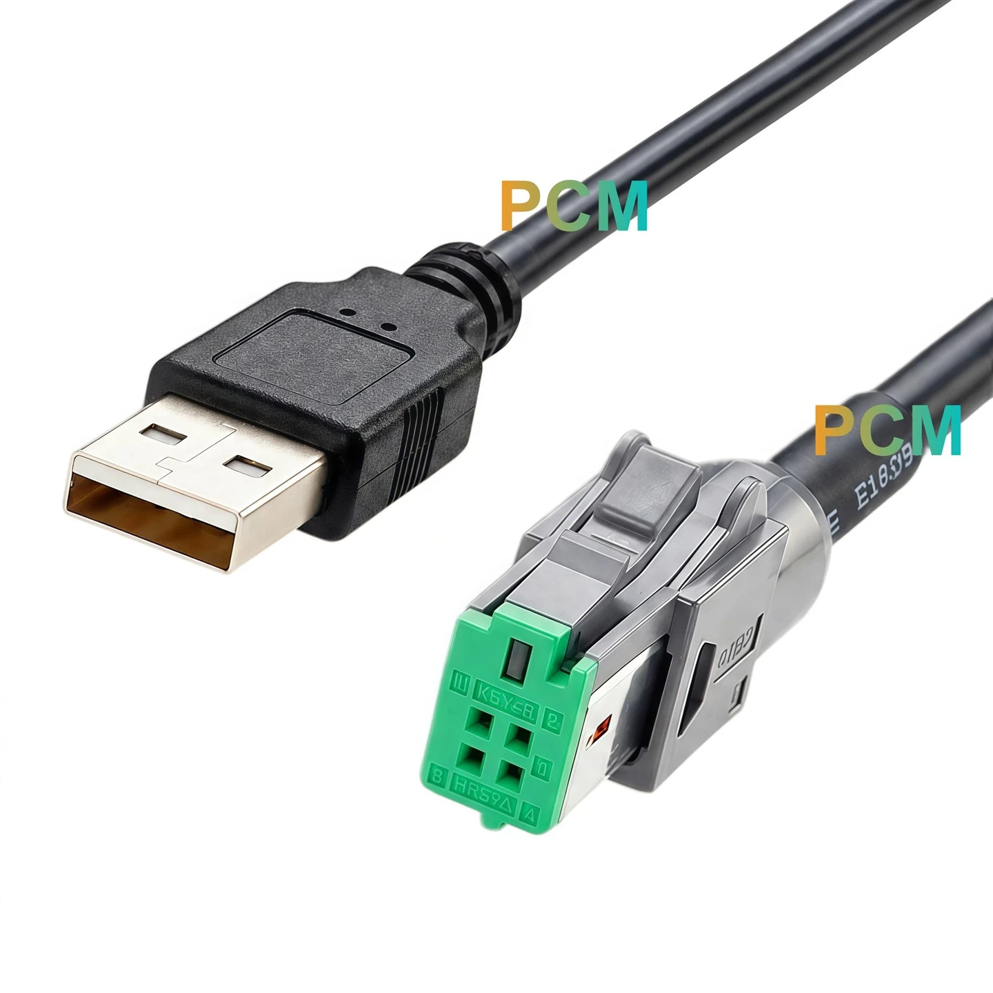
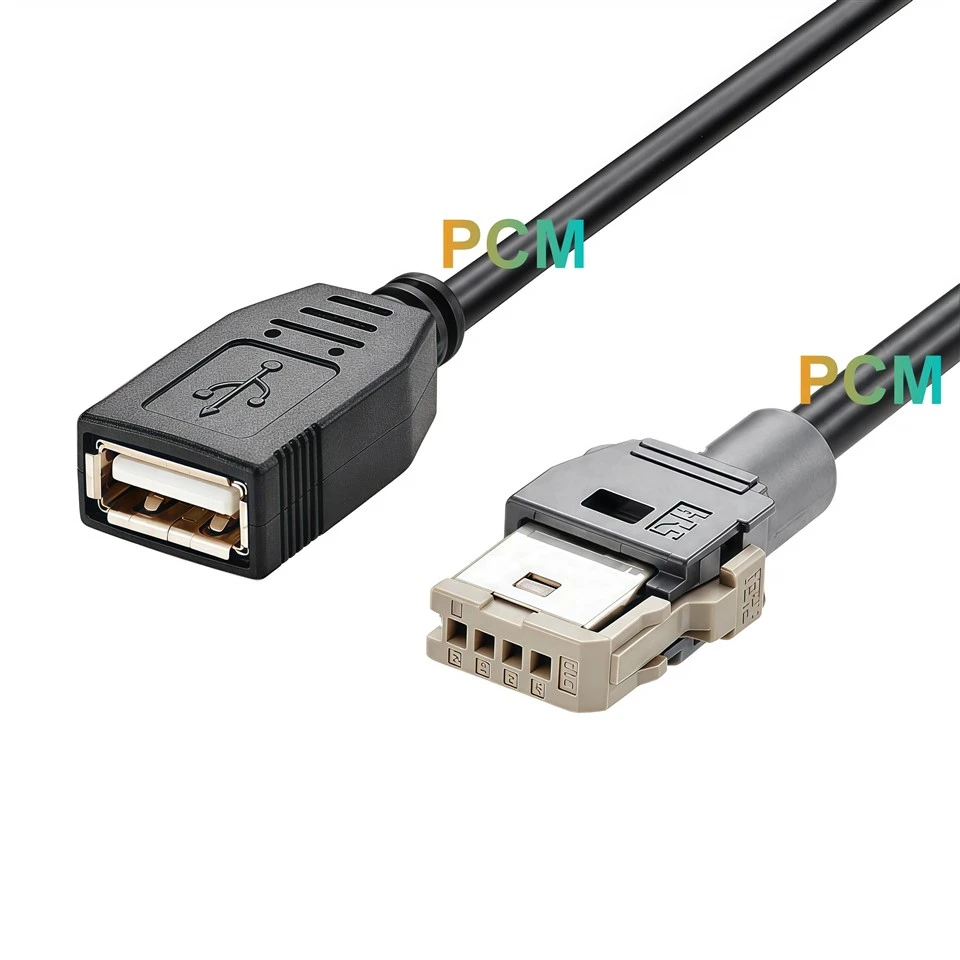
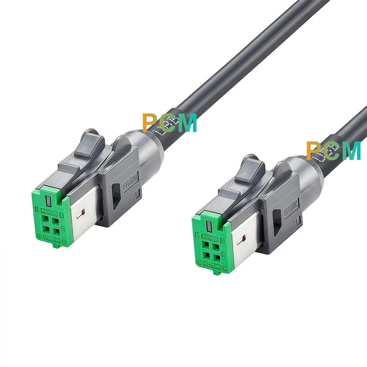
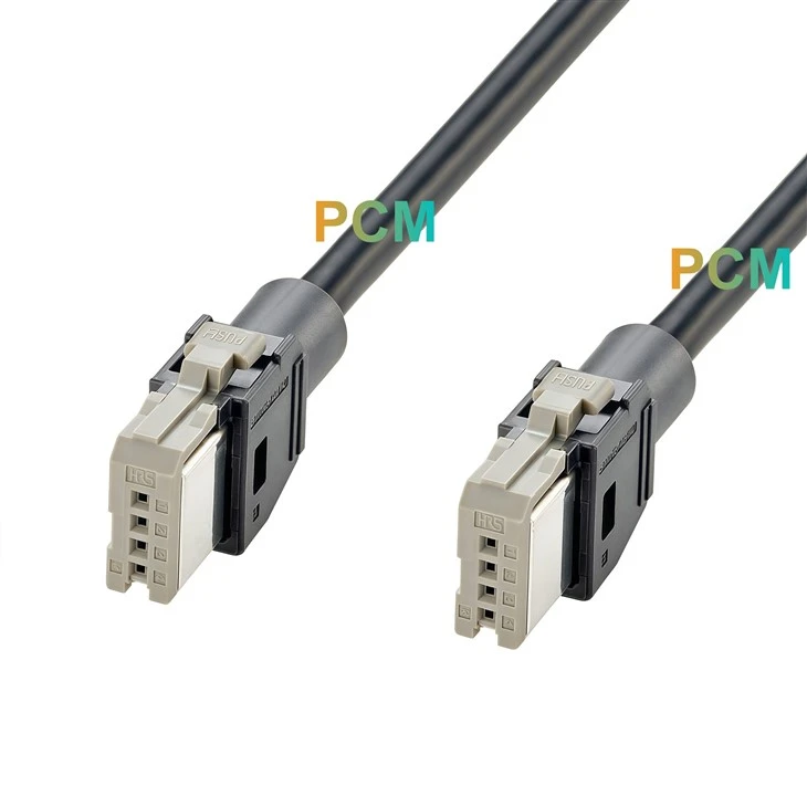
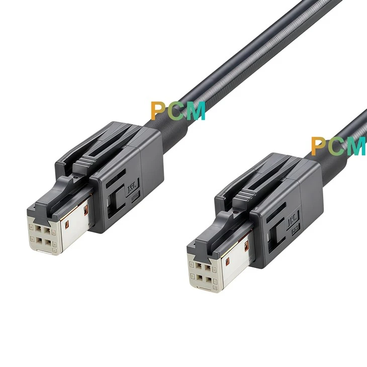
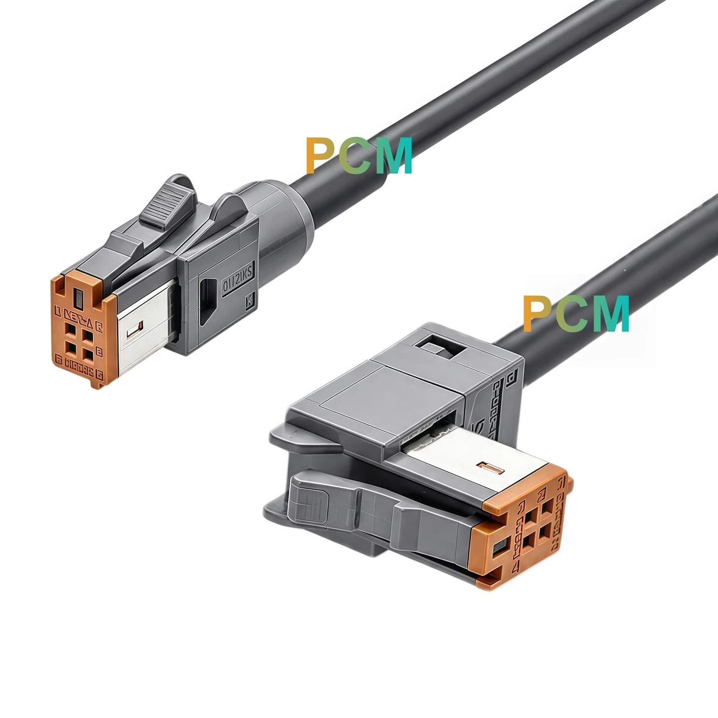
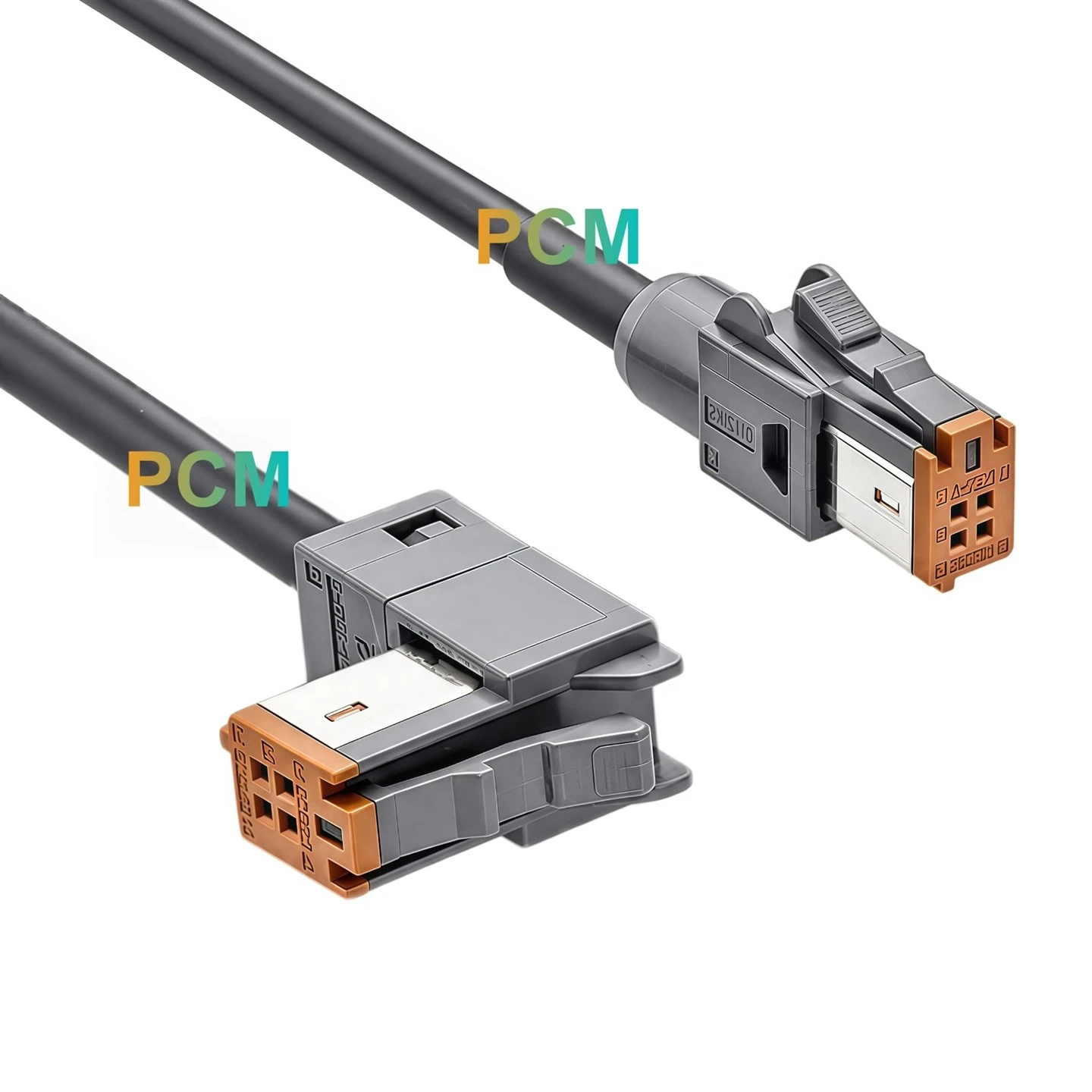
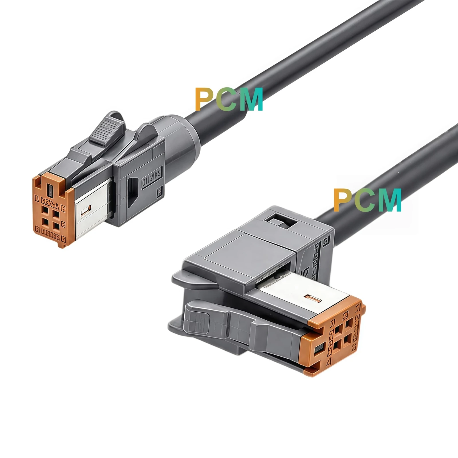
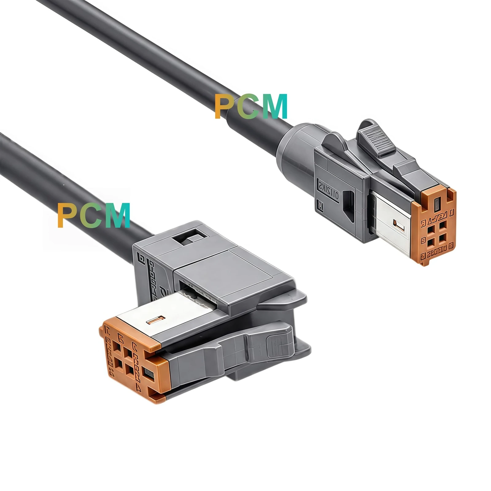
Both cable ends use the Hirose GT17HN-4DS-2C(A) connector, but their housing references are not interchangeable specifications. P1 is assembled with GT17HNS-4DS-HU, while P2 uses GT17HN-4DS-HU. This distinction is central to the product configuration and should be maintained in component procurement, assembly instructions and replacement part identification. Specifying only the connector model would leave out an important part of the finished assembly design.
Straight to Right Angle Connection Layout
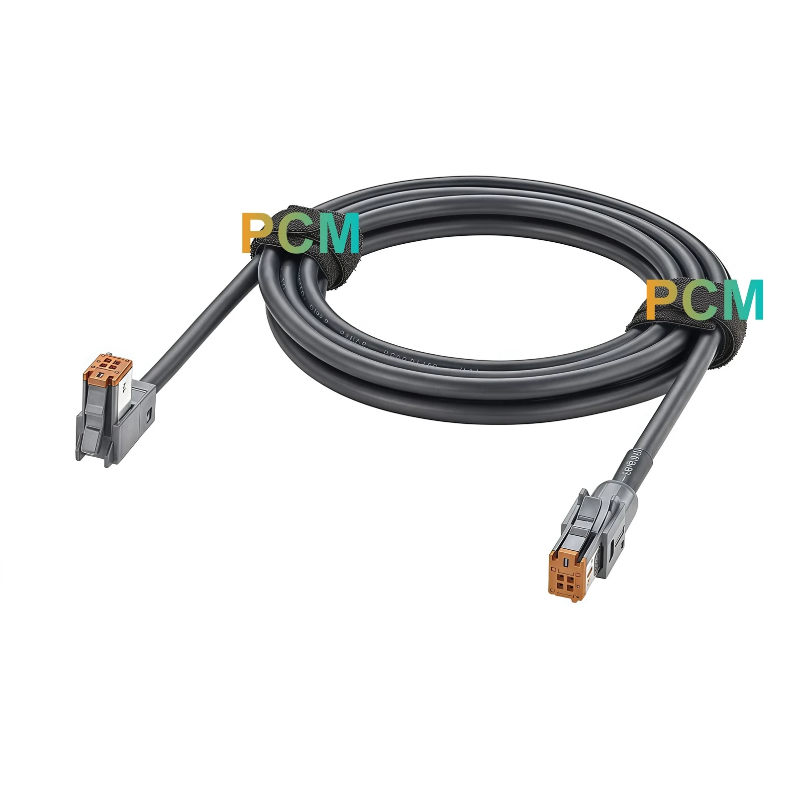
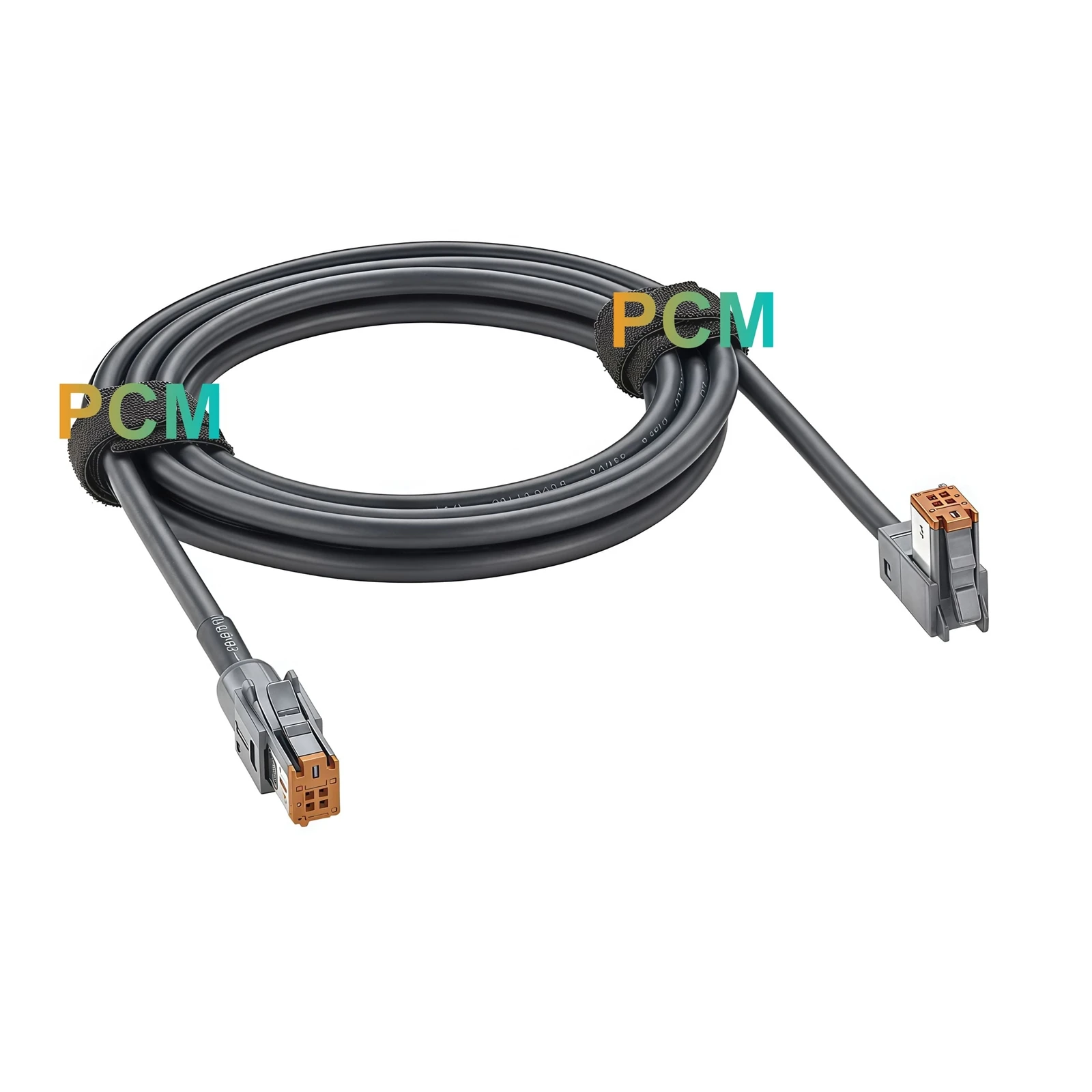
The two ends are designed with different connector orientations. P1 has a straight arrangement, while P2 uses a right angle arrangement. This configuration accommodates equipment connection points that require different cable entry directions. Instead of using identical terminations at both ends, the assembly follows the mechanical layout defined in the engineering drawing. Connector orientation should therefore be considered together with the housing reference when checking available installation space and cable routing.
Dual Row A Key Contact Configuration
Each connector uses a four contact dual row arrangement with A Key identification. The brown keyed inserts provide a visible reference for the specified mating configuration. Both ends follow the same four signal assignments, connecting VCC, D-, D+ and GND through corresponding pin positions. The connector keying and contact arrangement provide the mechanical and electrical references required for mating component selection and wiring verification.
Cable Transition and Protective Sleeve
The main cable has a specified 4.6mm outer diameter and a black jacket made from 45P PVC compound. A separate single wall casing is specified near the connector transition, with a 5.0mm outer diameter and 20mm length. This additional component forms part of the mechanical assembly rather than the main cable construction. Its dimensions should be considered when evaluating connector clearance, cable routing and the space available around the equipment interface.
Applications and OEM Customization
OEM Development and Manufacturing
Premier Cable supports drawing evaluation, prototype preparation, sample inspection and mass production. Labels, product identification and packaging can also be arranged according to confirmed customer specifications.
Housing and Connector Configuration
Premier Cable supports reviews of connector models, housing references, keying arrangements and termination orientation. Alternative configurations can be evaluated against the required mating interfaces and mechanical drawings.
Cable and Wiring Modifications
Premier Cable can review cable length, jacket material, shielding construction, conductor arrangement and pin assignment according to project requirements. Changes to electrical characteristics require engineering confirmation before production.
Connections Between Two GT17HN Equipment Interfaces
PCM-ZC-0243 is intended for equipment layouts that use GT17HN A Key interfaces at both ends. The matching connector model and defined pin arrangement provide a specified connection between two equipment side interfaces without introducing a different connector family.
Different Cable Entry Directions
The straight P1 termination and right angle P2 termination address installation layouts where the two connection points have different orientation requirements. This arrangement can be evaluated for compact equipment, internal wiring and electronic module connections where connector exit direction affects cable routing.
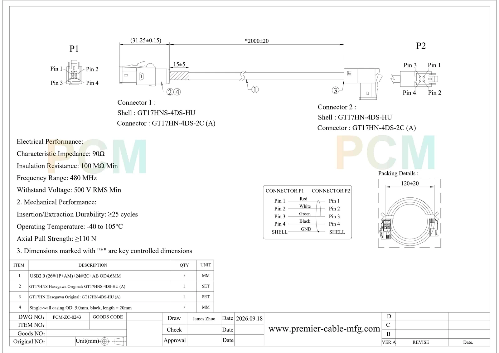
Product Drawing
Product FAQ
Do both ends use the same A Key connector ?
Yes. Both ends use the GT17HN-4DS-2C(A) connector with a four contact dual row arrangement. Their housing references and installation orientations are different.
Why are two different housing part numbers used ?
The assembly specifies GT17HNS-4DS-HU at P1 and GT17HN-4DS-HU at P2. These references identify the different housing configurations required by the two equipment connection points.
What makes PCM-ZC-0243 different from a conventional GT17HN cable ?
PCM-ZC-0243 uses Hirose GT17HN connectors at both ends, but combines two different housing configurations and connector orientations in one assembly. P1 is straight, while P2 is right angle.
How should the cable be routed during equipment installation ?
The straight P1 end and right angle P2 end should be positioned according to the equipment interface layout. The 2000±20mm cable length and connector dimensions should be considered when planning the routing path.
Can Premier Cable modify the two connector configurations ?
Yes. Premier Cable can evaluate different housing combinations, connector orientations, cable lengths and wiring requirements based on engineering drawings or samples. Prototype and production arrangements are available after design confirmation.

Hot Tags: hirose gt17hn straight to right angle cable, China hirose gt17hn straight to right angle cable manufacturers, suppliers, factory