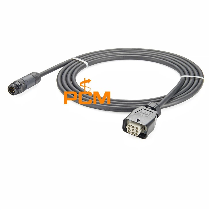

Hey everyone! I'm a supplier of AISG RET cables, and today I wanna talk about how to test the functionality of an AISG RET cable. It's super important to make sure these cables work well before they're put into use, so let's dive right in.
Why Testing Matters
First off, you might be wondering why we even need to test these cables. Well, AISG RET cables are used in all sorts of important communication and control systems. If a cable isn't working properly, it can lead to all kinds of problems, like signal loss, inaccurate data transmission, and even system failures. That's why we need to test them thoroughly to ensure they meet the required standards and can perform their job effectively.
Tools You'll Need
Before we start testing, we need to gather the right tools. Here's what you'll typically need:
- Multimeter: This is a must-have tool for electrical testing. It can measure voltage, current, and resistance, which are all crucial parameters when testing cables.
- Cable Tester: A specialized cable tester can quickly check the continuity of the cable, making sure there are no breaks or shorts in the wires.
- Signal Generator: This device can generate different types of signals to test how well the cable can transmit them.
- Oscilloscope: It allows you to visualize the electrical signals passing through the cable, helping you spot any irregularities.
Visual Inspection
The first step in testing an AISG RET cable is a simple visual inspection. Take a close look at the cable for any obvious signs of damage, such as cuts, frays, or kinks. Check the connectors as well. Make sure they're clean, free of corrosion, and properly attached to the cable. If you notice any damage, it's likely the cable won't work properly, and you might need to replace it.


Continuity Testing
Continuity testing is one of the most basic but important tests. It checks if there's a complete electrical path through the cable. To do this, you can use a multimeter or a cable tester.
- Using a Multimeter: Set the multimeter to the continuity mode. Touch one probe to one end of the wire in the cable and the other probe to the corresponding end at the other side of the cable. If the multimeter beeps or shows a very low resistance value, it means there's continuity, and the wire is intact. Repeat this process for each wire in the cable.
- Using a Cable Tester: Connect the cable tester to both ends of the cable. The tester will send a signal through the wires and indicate if there's continuity or not. This method is faster and more convenient, especially for cables with multiple wires.
Resistance Testing
Resistance testing is another important aspect. Each wire in the cable should have a specific resistance value within a certain range. Using a multimeter set to the resistance mode, measure the resistance of each wire. Compare the measured values with the manufacturer's specifications. If the resistance is too high or too low, it could indicate a problem with the cable, such as a damaged wire or a poor connection.
Signal Transmission Testing
Once we've checked the continuity and resistance, it's time to test how well the cable can transmit signals. This is where the signal generator and oscilloscope come in handy.
- Setting Up the Test: Connect the signal generator to one end of the cable and the oscilloscope to the other end. Generate a simple signal, like a sine wave, using the signal generator.
- Analyzing the Signal: Look at the oscilloscope screen to see the signal that has passed through the cable. The signal should be similar to the one generated by the signal generator, with minimal distortion. If you notice any significant changes in the shape, amplitude, or frequency of the signal, it means the cable might have problems transmitting the signal properly.
Testing Different Types of Cables
We offer different types of AISG RET cables, such as the RET AISG Cable Assembly Right Angle, RET AISG Y Splitter Cable 8 Pin Male To Female, and Molded AISG Control Cable Assembly 8 PIN DIN. The testing process is generally the same for all these cables, but there might be some specific considerations.
- Right Angle Cables: The right angle design can sometimes affect the signal transmission, especially if the bend is too sharp. Make sure to test the cable at different angles to ensure consistent performance.
- Y Splitter Cables: These cables split the signal into multiple paths. When testing, you need to check each branch of the cable separately to make sure all the connections are working properly.
- Molded Cables: The molded design provides better protection, but it can also make it harder to access the wires for testing. Use the appropriate testing tools to ensure accurate results.
Final Checks
After completing all the tests, do a final check to make sure everything is in order. Double - check the test results and make sure they meet the required standards. If the cable passes all the tests, it's ready to be used. If not, you might need to troubleshoot further or replace the cable.
Conclusion
Testing the functionality of an AISG RET cable is a crucial process to ensure its reliability and performance. By following the steps outlined above, you can identify any potential problems and make sure the cable is working as it should.
If you're interested in purchasing high - quality AISG RET cables or have any questions about the testing process, feel free to get in touch with us. We're always here to help you find the right solutions for your needs.
References
- Electrical Testing Handbook for Communication Cables
- AISG RET Cable Manufacturer's Technical Documentation