A variable frequency drive (VFD) is an electronic device used to adjust the speed and torque of a motor. It controls the running speed of the motor by adjusting the power frequency and voltage input to the motor to achieve precise control of the motor. The main functions of the variable frequency drive include:
1. Speed control:
By changing the power frequency, the variable frequency drive can control the speed of the motor to adapt to different working requirements.
2. Torque control:
Adjust the output torque of the motor to meet the requirements of load changes.
3. Energy efficiency optimization:
The variable frequency drive can adjust the running speed of the motor according to the load requirements, reduce energy waste, and improve energy utilization efficiency.


4. Soft start and soft stop:
By gradually increasing or decreasing the speed of the motor, the impact on the mechanical system during starting and stopping is reduced, and the service life of the equipment is extended.
5. Protection function:
Provide protection functions such as overload, overvoltage, undervoltage, and short circuit to ensure the safe operation of the motor and the variable frequency drive.
6. Remote control and monitoring:
Through communication interfaces (such as Modbus, Profibus, etc.), the variable frequency drive can be remotely monitored and adjusted with other control systems.
Inverters are widely used in various industrial and commercial scenarios, including manufacturing, construction, HVAC systems (heating, ventilation and air conditioning), water treatment and transportation, to improve the flexibility and operating efficiency of equipment.
Which connector interfaces are used in the inverter?
In variable frequency drive (VFD) systems, common connector interfaces include:
1. Power connector:
Main power input: used to connect to the grid power supply, including high-voltage and low-voltage input terminals, usually screw terminals or crimp terminals.
Output terminals: connected to the output terminals of the motor, transmitting the power regulated by the variable frequency drive.
2. Control interface:
Digital input/output (DI/DO): used to connect control devices such as switches, buttons, and indicator lights.
Analog input/output (AI/AO): used to connect analog signal devices such as sensors and instruments, transmitting speed, temperature and other signals.
Relay output: used to connect alarm lights or external control systems to provide status feedback and alarm signals.
3. Communication interface:
RS485/RS232: used for data communication, connecting PLC, HMI (human-machine interface) or other control systems, supporting protocols such as Modbus, Profibus, etc.
Ethernet: used for network communication, supporting industrial Ethernet protocols such as Profinet, Ethernet/IP, etc.
CANopen: used for control network communication between devices, common in industrial automation applications.


4. Terminals and plugs:
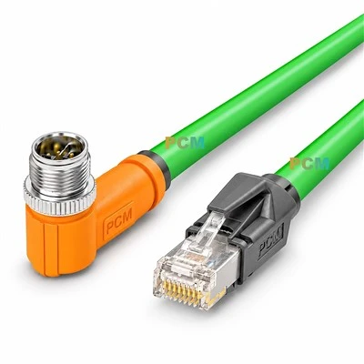
M12/M16 connectors: used to connect sensors, actuators and other devices, providing a stable electrical connection.
Cable connectors: used to connect the cable of the inverter and the motor or other external devices.
5. Programming interface:
USB interface: used to connect programming tools and PCs for parameter setting and data upload/download.
Handheld programmer interface: used to set and adjust inverter parameters directly on site.
These interfaces and connectors play a key role in the installation and maintenance of the inverter, ensuring effective communication and operation between the inverter and the control system, motor and other equipment.