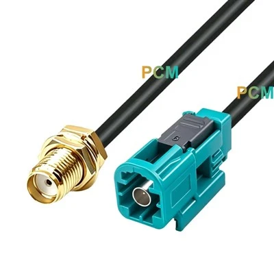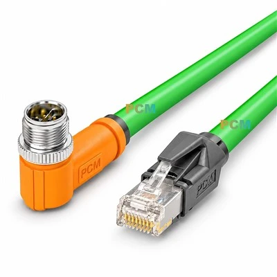
After the engine has been installed and can be started normally, proceed to: connect the various sensors, instruments (speed, oil pressure, water temperature, oil volume, rudder angle, lift angle, etc.) and multi-function display (MFD) of the outboard motor to the console. The following is a list of cables/connectors to be prepared and the details that must be paid attention to when wiring, giving you a "material preparation + construction" manual that you can use once.
1. First determine which line you are on
| Instrumentation System | Typical Year / Model | Signal Type | Core Wiring/Cabling | Primary Connectors |
|---|---|---|---|---|
| Pure Analog Gauges (Needle Type) | Older 2-stroke, Budget 4-stroke | Voltage / Frequency / Variable Resistor | 4–8 core jacketed wire, 18–20 AWG | Engine Side: Yamaha 10-Pin, Mercury 8-Pin, Honda 6-Pin Gauge Side: #8 ring / spade terminals |
| Brand-Specific Digital Bus (Yamaha Command-Link, Mercury SmartCraft, Suzuki SMIS, Honda iST, etc.) |
2004–2020 Mainstream Models | CAN-bus | Brand-specific CAN harness (Typically 2x22 AWG data + 2x18 AWG power) | Engine Side: Brand-specific round waterproof plug Bus: Deutsch DT-04/DT-06 2-pin or AMP Superseal |
| NMEA 2000 (or retrofit from above brand buses) |
2010 to Present New Engines & MFDs | CAN-bus | Backbone + Drop cables, 5-core 22 AWG shielded twisted pair | M12 A-code 5-pin Micro-C / Mid-C |
| Full Electronic Shift + Digital Steering Systems (Mercury DTS, Yamaha Helm Master EX, etc.) |
2018+ High-End Engines | CAN or Ethernet | Twisted pair CAN + Shielded CAT5e/6e | Round waterproof plugs; Some Helm Master EX use standard RJ45 |
2. Essential "Shopping List"
The following is an example of NMEA2000 / a certain brand CAN‑bus modification. For a pure analog meter, you only need to buy the corresponding wiring harness + the ring terminal behind the meter.
1. Backbone Cable (5-core shielded)
- Length is reserved based on the straight-line distance from the ship's bridge to the stern + 30%
- Rated voltage ≥ 60V, oil-resistant PVC or TPU sheath
2. T‑Connector×N
- One T is required for each device (MFD, engine gateway, oil level sensor, etc.)
3. Drop Cable (branch line)
- One cable for each device, length ≤ 6m
4. 2 120Ω Termination Resistors
- Must be installed at both ends of the Backbone
5. Power Tee + 5A Marine Fuse
- Take power within 7in from the battery and inject +12V / GND into the Backbone
6. Outboard Engine Gateway (Engine Interface Cable / Gateway)
- Convert Yamaha 6‑Pin, Mercury 10‑Pin ... to NMEA2000
7. Several Deutsch DT, AMP Superseal or Micro‑C field-assembled plugs
- Convenient for you to cut the wire to a fixed length and crimp it on site
8. Waterproof heat shrink tubing, butyl adhesive tape, strapping seat/hose clamp, identification sleeve

3. 9 hard rules for wiring (many people have suffered losses)
| # | Key Point | Why This Matters |
|---|---|---|
| 1 | Run the backbone in a single straight line - no branches | Star/ring CAN topologies cause signal reflection & data errors |
| 2 | Install only two 120 Ω terminators - one at each end | Missing terminator = signal reflection; Extra terminators = impedance mismatch |
| 3 | Max drop length ≤ 6 m, backbone ≤ 100 m | Exceeding causes latency/voltage drop; Small boats rarely exceed, but know limits |
| 4 | Keep ≥ 15 cm clearance from high-voltage ignition wires | Prevents EMI interference; Ignition wires carry transient tens of thousands of volts |
| 5 | Apply thin layer of silicone grease / marine dielectric grease to all connectors | Prevents salt corrosion + ensures future serviceability |
| 6 | Leave a "U"-shaped slack loop for engine tilt/trim movement | Prevents cable damage during engine articulation |
| 7 | Secure with soft-edged clamps every ≤ 40 cm - never zip-tie directly | Reduces vibration damage; Zip ties cut through jacket insulation |
| 8 | Fuse power tap ≤ 10 cm from backbone connection | Prevents short circuits from damaging entire backbone |
| 9 | Cap unused T-connectors/ports with dust plugs | Keeps moisture, dust, and insects out during storage |

4. Brand-specific parts examples (most common)
| Brand | Outboard Plug → NMEA/Gauge Adapter | Common Part Numbers | Notes |
|---|---|---|---|
| Yamaha | 6Y8‑82521‑11 (Command Link Gateway) 6X6‑82553‑00 (Digital Throttle/Shift) |
Waterproof 4‑Pin / 6‑Pin | New EX models add separate RJ45 connectors |
| Mercury | 8M0151744 (SmartCraft‑to‑NMEA 2000) 84‑879979T07 (DTS Main Harness) |
10‑Pin Round | Older engines may require "blue-cable" adapter |
| Suzuki | 990C0‑88149 (SMIS Gateway) | Denso 4‑Pin | Compatible with 2008+ EFI engines |
| Honda | 06327‑ZY3‑760 (iST CAN Harness) | 6‑Pin | Requires separate ACC (accessory) power wire |
5. Check the "Golden 5 Steps" for Power On
- Before power on: Use a multimeter to measure Backbone +12V and Ground to ensure <14V and correct polarity
- Power on for the first time: Disconnect the engine ignition first, power on the bus alone, and observe whether the MFD self-checks normally
- Connect the gateway: Plug in the outboard motor gateway again to see if "ENGINE ONLINE" appears on the MFD
- Start the engine: Confirm that the speed, water temperature, and oil pressure have readings immediately
- Test one by one: Increase the throttle, shift forward/reverse gear, and see if the gear status is refreshed in real time
After everything is normal, tidy up the wiring harness, buckle the sheath, and finally spray a thin layer of waterproof spray on all plugs.
Summary
- Material preparation: trunk line, drop line, T-connector, termination resistor, Power Tee, brand gateway, corresponding connector.
- Wiring focus: straight line topology, terminal impedance, line length limit, EMI spacing, flexible margin, anti-corrosion treatment.
Follow the above, the deck is clean and the signal is stable. In the future, adding a speaker or radar can easily "extend a section of T" to the Backbone.