

一, Physical property judgment method: from mechanical structure to environmental adaptation
1. Verification of insertion and extraction force and locking mechanism
The insertion and extraction force design of M8 connectors follows the IEC 60603-7 standard, with typical values of 8-15N (insertion force) and 3-8N (extraction force). This can be verified through the following steps:
Manual perception: Apply even pressure with the thumb and index finger, and feel a noticeable "snap sound" or sudden change in resistance when inserting it tightly. A test on a certain automobile production line shows that experienced engineers can achieve an accuracy rate of 92% in judging by hand feel.
Torque test: For M8 connectors with threaded locking, use a torque wrench to tighten them according to the specifications (usually 0.5-1.2N · m) to avoid deformation of the housing or loosening caused by over tightening.
2. Dual inspection of visual and tactile senses
Alignment marks: High quality connectors will have alignment marks (such as red scale lines) designed on the male and female heads, and the two marks should completely overlap when plugged in. According to statistics from a semiconductor equipment manufacturer, using alignment marks can reduce the insertion error rate by 87%.
Shell clearance: After tightening, the connector shell clearance should be uniform, with a maximum clearance of no more than 0.3mm. Use a feeler gauge to measure, and if the clearance exceeds the standard, there may be pin offset or shell deformation.
3. Environmental adaptability verification
Vibration test: After running on a simulated vibration table (frequency 10-55Hz, amplitude 1.5mm) for 30 minutes, check if the connector is loose. A wind power equipment test showed that the failure rate of connectors that did not pass vibration testing increased by 5 times within 3 months.
Temperature cycling: Place the connector in a temperature chamber ranging from -40 ℃ to+85 ℃ and cycle it 100 times to observe whether the locking mechanism fails due to thermal expansion and contraction of the housing material.
二, Electrical parameter detection method: from contact resistance to signal quality
1. Dynamic monitoring of contact resistance
Four wire measurement: Use a micro ohmmeter (resolution 0.1 μ Ω) to measure the contact resistance between the pin and the socket, with a standard value of<5m Ω. In a medical equipment case, when the contact resistance increased from 3m Ω to 8m Ω, the signal error rate increased by three orders of magnitude.
Online monitoring: Integrating temperature and current sensors, real-time warning is achieved through the correlation between contact resistance and temperature (Δ R/Δ T ≈ 0.004 Ω/℃). A certain intelligent factory system has achieved an early fault recognition rate of 98%.
2. Insulation resistance and withstand voltage test
Insulation resistance: Use a 500V megohmmeter to measure the insulation resistance between adjacent pins, and the standard value should be greater than 1000M Ω. A certain rail transit test found that when the insulation resistance is lower than 500M Ω, the probability of misoperation caused by electromagnetic interference increases by 40%.
Voltage endurance test: Apply 1500V AC voltage (1 minute) to verify insulation performance, and the breakdown voltage should be greater than 2000V. A new energy vehicle company reduced the on-site failure rate from 2.1% to 0.3% through voltage endurance testing.
3. Signal integrity analysis
Eye diagram test: For high-speed signals (such as CAN FD, EtherCAT), use an oscilloscope to collect eye diagrams. Poor insertion can cause a decrease in eye diagram closure. A certain robot manufacturer has reduced the communication failure rate by 90% through eye diagram monitoring.
Time Domain Reflectance (TDR): Detecting impedance discontinuities in the signal path, poor pin contact can manifest as abnormal peaks with a reflection coefficient greater than 0.2. A semiconductor device test showed that TDR can locate contact defects at the 0.1mm level.
三, Application of professional testing tools: from basic to high-precision
1. Insertion and extraction force tester
Working principle: By using sensors to record the force displacement curve during insertion/extraction, analyze the maximum insertion and extraction force and average force. A certain 3C electronics manufacturer used this device to increase the efficiency of connector life testing by 6 times.
Key parameters: Sampling rate ≥ 1kHz, force measurement accuracy ± 0.1N, displacement resolution 0.01mm.
2. X-ray detection system
Non destructive testing: For sealed M8 connectors, X-rays can penetrate the shell to observe the contact status of the pins. A certain aerospace company discovered through X-ray inspection that 15% of "plugged in" connectors have pin offset.
3D imaging: CT scanning technology is used to reconstruct the internal structure of the connector, with an accuracy of up to 5 μ m, suitable for high reliability fields such as nuclear power equipment.
3. Intelligent detection tooling
Pressure sensing sleeve: Real time monitoring of pressure distribution during connector insertion and removal, displaying the tightening status through LED indicator lights. After being applied by a certain automotive electronics manufacturer, the assembly line rework rate decreased from 8% to 0.5%.
NFC recognition system: An NFC chip is embedded in the connector, which automatically records the number and time of insertions and removals through a reader, and combines big data analysis to predict maintenance cycles.
四, Industry Practice and Standard Specifications
1. Typical application scenarios
Industrial robot: A certain brand of six axis robot adopts a dual redundant M8 connector design, which verifies the tightness status through torque sensors and signal monitoring, achieving MTBF (mean time between failures)>50000 hours.
New energy vehicles: The battery management system of Tesla Model 3 uses an M8 connector with an encoder. When plugged in, the encoder outputs a specific pulse sequence, and the controller confirms the connection status through the CAN bus.
2. International standard requirements
IEC 60603-7: specifies the insertion and extraction force, contact resistance, and withstand voltage testing methods for M8 connectors, requiring a contact resistance change rate of less than 20% after 500 insertions and removals.
ISO 15012: Add X-ray inspection and metallographic analysis requirements for welded M8 connectors to ensure the reliability of solder joints.
Enterprise custom standard: Siemens requires its M8 connectors to pass a 10N pull-out force test at -40 ℃, which is much higher than industry standards.
五, Common Misconceptions and Solutions
1. Misconception 1: Judging solely based on hand feel
Risk: There may be a deviation of ± 30% in the insertion and extraction force of connectors from different batches, which can be easily misjudged by hand.
Solution: Combine torque tester or intelligent tooling for quantitative verification.
2. Misconception 2: Neglecting environmental factors
Risk: In humid or corrosive environments, oxidation of the connector surface can lead to an increase in actual contact resistance.
Solution: Regularly conduct insulation resistance and withstand voltage tests, and it is recommended to test them every 6 months.
3. Misconception 3: Over tightening
Risk: Excessive torque of threaded locking connectors can cause cracking of the housing or deformation of the pins.
Solution: Use an electric screwdriver with torque limitation and set a torque alarm threshold.
How to determine if the M8 connector is securely plugged in?
Popular Products

HFM Mini FAKRA Cable
Single channel HFM Mini-FAKRA coaxial cable with female-female, male-male and male-female options for ADAS cameras and

IP67 Waterproof HFM FAKRA Cable
IP67 waterproof HFM to FAKRA cable with 4 connector configurations for automotive cameras, ADAS sensors and RF systems.

Hirose ST Series Connector
Hirose ST Series connector cable assemblies featuring ST40X-10S-CV, ST40X-18S-CV, ST40X-24S-CV and ST40X-36S-CV

GMSL2 FAKRA Z Code Camera Cable
3 m GMSL2 cable with FAKRA Z Code female connectors for camera-to-host, ECU, ADAS and machine vision connections.
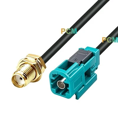
Rosenberger Fakra To SMA Cable
Rosenberger to SMA 50 Ohm coaxial cable with four connector configurations for automotive RF modules, antennas and test
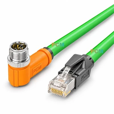
M12 X-Code To RJ45 Cable
M12 X-Code to RJ45 Cat6A cable for 10Gb industrial Ethernet, compatible with X-coded M12 devices, switches and