DIN 13 Pin Right Angle Cable: Space-Saving Cable Assembly for Industrial Control Equipment
A practical guide to DIN 13 pin right angle cable assemblies for compact equipment wiring, control cabinets, medical and laboratory devices, test instruments, robotics, and OEM electronic systems.
A DIN 13 pin right angle cable is designed for equipment that needs multi-core signal transmission in a compact installation space.
The 13-pin configuration can support multiple circuits in one cable assembly, including power, control signals, feedback signals, and data-related wiring depending on the equipment pinout.
A 90-degree connector helps reduce rear clearance, avoid sharp cable bending, protect the connector interface, and improve cable routing inside control cabinets or equipment housings.
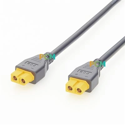
Premier Cable PCM-0951 uses dual 90° DIN 13 pin male connectors with UL2464 24AWG 13-core cable, black jacket, 6.5 mm OD, and 6 ft standard length.
Before ordering, buyers should confirm connector gender, right-angle exit direction, cable length, pinout, shielding requirement, wire gauge, and equipment application.
Definition: A DIN 13 pin right angle cable assembly is a multi-core circular connector cable with 13 contacts and a 90-degree cable exit. It is used when equipment needs integrated power, signal, control, or data wiring in limited installation space.
📋 Contents
What Is a DIN 13 Pin Right Angle Cable?
A DIN 13 pin right angle cable is a multi-core circular connector cable designed for equipment that requires several circuits within one compact cable assembly. With 13 contacts, the connector can be used for power, control signals, feedback signals, and data-related wiring depending on the equipment design and pin assignment.
Compared with simple two-wire or low-pin-count cables, a 13-pin DIN cable can reduce wiring complexity by integrating multiple functions into one connector. This is useful in industrial control systems, motion control devices, medical and laboratory equipment, audio-video systems, test instruments, communication devices, and OEM electronic equipment.
The right angle design changes the cable exit direction by 90 degrees. Instead of projecting straight backward from the equipment, the cable can turn naturally along the side of the device, cabinet wall, rack frame, or machine panel. This makes the cable more suitable for installations where rear clearance is limited.

Image 1: Full PCM-0951 DIN 13 pin right angle cable assembly

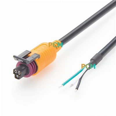
Image 2: DIN 13 pin male connector detail and right-angle exit
Why Use a 90-Degree DIN Connector?
In many industrial and electronic devices, cable routing is not only an electrical issue. It is also a mechanical design problem. Equipment may be installed close to a cabinet wall, inside a control box, behind a rack panel, or inside a compact machine housing. A straight connector may require too much rear clearance and can force the cable to bend sharply.
A 90-degree DIN connector helps the cable exit parallel to the equipment surface. This reduces the required installation depth and allows the cable to follow the equipment edge or cabinet side more naturally.
Important: Right angle direction must be confirmed before ordering. Depending on the device socket orientation, the cable may need to exit upward, downward, left, or right. A wrong 90° direction can make the cable difficult to install even if the connector type is correct.
| Design Benefit | Why It Matters in Equipment Wiring |
|---|---|
| Saves rear space | The cable exits sideways instead of straight backward, helping equipment fit closer to walls, panels, or cabinet doors. |
| Reduces cable bending stress | The cable turns naturally from the connector instead of being forced into a tight bend immediately after the plug. |
| Protects the connector interface | Less mechanical force is applied directly to the connector tail, reducing the risk of looseness or connector damage. |
| Improves cable management | The cable can be routed neatly along the edge of equipment, inside control cabinets, or around internal machine structures. |
| Supports compact equipment design | Right-angle cable assemblies are useful in rack devices, embedded equipment, control boxes, and devices with limited connector clearance. |
DIN 13 Pin Right Angle Cable vs Straight DIN Cable
Both straight DIN cables and right angle DIN cables can be used for signal and power interconnection, but the mechanical installation environment determines which structure is more suitable. For open space and simple bench-top equipment, a straight connector may be enough. For compact devices, rear-mounted sockets, cabinet installation, and wall-mounted equipment, a right angle connector usually provides better routing.
| Comparison Item | Straight DIN Cable | 90° Right Angle DIN Cable |
|---|---|---|
| Rear clearance | Requires more space behind the equipment | Better for limited rear space |
| Cable bending | May create sharp bends in compact installations | Allows natural cable turn from the connector |
| Connector stress | Cable weight may pull directly on the connector tail | Reduces tail stress and improves routing stability |
| Cable management | Cable may protrude from the device | Cable can run along cabinet or equipment edges |
| Best use case | Open installation, testing bench, non-space-limited equipment | Control cabinet, rack device, wall-mounted unit, compact equipment |
Buyer Tip: If the equipment socket is located on the rear panel and the device is installed close to another surface, a right angle DIN cable can help avoid cable compression and connector stress.
PCM-0951 Product Configuration
Premier Cable PCM-0951 is a DIN 13 pin right angle male-to-male cable assembly designed for compact wiring applications. Both ends use 90° right angle DIN 13 pin male connectors, making the cable suitable for equipment where straight connectors would require too much installation space.
| Parameter | Specification |
|---|---|
| Premier Cable Part Number | PCM-0951 |
| Product Name | DIN 13 Pin Right Angle Cable |
| Connector A | 90° Right Angle DIN 13 Pin Male |
| Connector B | 90° Right Angle DIN 13 Pin Male |
| Cable Type | UL2464 24AWG × 13 Core |
| Cable Outer Diameter | OD: 6.5 mm |
| Cable Color | Black |
| Standard Length | 6 feet |
The UL2464 24AWG 13-core cable construction provides multiple internal conductors for equipment that needs integrated wiring in a single cable assembly. The black jacket is suitable for professional equipment, control systems, and OEM device integration.

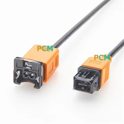
Image 3: PCM-0951 complete cable assembly

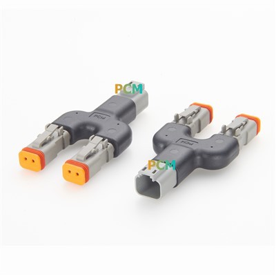
Image 4: Right angle DIN cable used in compact equipment wiring
Typical Applications
DIN 13 pin right angle cable assemblies are used in equipment that needs multi-core wiring, compact routing, and reliable connector positioning. The 13-pin interface makes the cable suitable for integrated power, control, feedback, and data-related connections depending on the device design.
| Application | How the Cable Is Used | Buyer Focus |
|---|---|---|
| Industrial Automation | Connects control modules, machine panels, PLC-related devices, and internal equipment interfaces | Pinout, cable direction, length, durability |
| Robotics and Motion Control | Used for control signals, feedback wiring, encoder-related circuits, or compact system interconnection | Flexibility, routing space, connector stress |
| Medical and Laboratory Equipment | Supports multi-core connections inside instruments, monitoring devices, and laboratory systems | Stable connection, compact installation, custom wiring |
| Test and Measurement | Connects signal instruments, DAQ-related devices, control boxes, and test platforms | Signal assignment, repeatability, cable length |
| Audio-Video and Communication Devices | Used for specialized multi-pin equipment interfaces where a DIN connector is specified | Connector type, shielding, pin definition |
| OEM Electronic Systems | Custom cable assembly for embedded devices, proprietary equipment, and compact electronic modules | Custom pinout, labeling, packaging, batch production |
Space-Constrained Equipment Is the Best Fit
The strongest reason to choose PCM-0951 is not only the 13-pin circuit count. It is the dual right angle structure. When equipment is mounted close to a wall, inside a rack, or within a control cabinet, the 90° cable exit helps prevent sharp cable bending and makes the wiring layout cleaner.
What Buyers Should Confirm Before Ordering
DIN 13 pin cables can be customized in many ways. Even when the connector is the same, the cable may still fail to fit if the angle direction, pinout, cable length, or wiring definition is different. The following details should be confirmed before placing an order.
| Information Needed | Why It Matters |
|---|---|
| Connector gender | Confirm whether the cable requires male-to-male, male-to-female, or female-to-female configuration |
| Pin count and connector face | DIN connectors may have similar shells but different pin layouts, so the connector face should be verified |
| Right angle direction | The cable exit may need to face up, down, left, or right depending on the equipment socket orientation |
| Cable length | The cable must be long enough for routing but not too long for compact cabinet wiring |
| Pinout or wiring diagram | Confirms whether the cable is straight-through or uses custom signal mapping |
| Wire gauge and cable structure | Affects signal type, flexibility, current handling, and mechanical durability |
| Shielding requirement | Important for signal stability in control equipment, test instruments, and communication devices |
| Application environment | Helps determine jacket material, strain relief, overmold, labeling, and packaging requirements |
Fast RFQ Tip: Send connector photos, equipment socket photos, cable length, pinout diagram, and the preferred right-angle exit direction. This helps avoid wrong samples and repeated engineering confirmation.
Custom DIN 13 Pin Cable Assembly Options
Premier Cable supports DIN 13 pin cable assemblies for industrial automation, medical and laboratory equipment, test instruments, audio-video systems, communication devices, and OEM electronic equipment. Custom cable assemblies can be produced based on drawings, samples, wiring diagrams, connector photos, or equipment requirements.
Connector Options
DIN 13 pin male connector
Right angle DIN connector
Male-to-male cable assembly
Custom connector orientation based on equipment layout
Cable Options
UL2464 24AWG × 13 core cable
6 ft standard length
Custom cable length
Black jacket, OD 6.5 mm
Assembly Options
Straight-through wiring
Custom pin assignment
Labeling and packaging
OEM and small-batch production support
Image Placement Suggestions
For this article, four images are enough. The goal is to help buyers quickly understand the product structure, connector direction, cable specification, and real installation value.
| Image Position | Recommended Image | Purpose |
|---|---|---|
| Image 1 | Full DIN 13 pin right angle cable product image | Shows the complete cable structure and dual 90° connector design |
| Image 2 | Close-up of the 13-pin connector face | Helps buyers confirm the connector pin layout and male interface |
| Image 3 | Close-up of right angle cable exit and black UL2464 cable jacket | Highlights space-saving design and cable construction |
| Image 4 | Application scene in control cabinet, medical instrument, or compact equipment | Shows why right angle routing is useful in space-limited installations |
Frequently Asked Questions
What is a DIN 13 pin right angle cable used for?
It is used for multi-core equipment wiring where several circuits must be integrated into one cable assembly. Common applications include industrial control systems, robotics, medical and laboratory equipment, test instruments, audio-video systems, communication devices, and OEM electronics.
Why choose a right angle DIN connector instead of a straight connector?
A right angle connector reduces rear clearance, helps avoid sharp cable bending, protects the connector tail, and makes cable routing easier in control cabinets, rack equipment, wall-mounted devices, and compact machine housings.
Is PCM-0951 a male-to-male cable?
Yes. PCM-0951 uses 90° right angle DIN 13 pin male connectors on both ends.
What cable is used for PCM-0951?
PCM-0951 uses UL2464 24AWG × 13 core cable with a black jacket and 6.5 mm outer diameter.
Can the cable length and pinout be customized?
Yes. Cable length and wiring can be customized based on customer drawings, equipment requirements, pinout diagrams, or samples. Right angle exit direction should also be confirmed before production.
What information should I provide for quotation?
Please provide connector photos, equipment socket photos, required cable length, pinout or wiring diagram, quantity, right angle exit direction, and application environment.
Need a DIN 13 Pin Right Angle Cable for Your Equipment?
Premier Cable supplies DIN 13 pin right angle cable assemblies for industrial automation, medical and laboratory equipment, test instruments, audio-video systems, communication devices, robotics, motion control, and OEM electronic equipment.
PCM-0951 DIN 13 pin right angle male-to-male cable
Dual 90° DIN 13 pin male connectors
UL2464 24AWG × 13 core cable, OD 6.5 mm, black jacket
6 ft standard length and custom length options
Custom pinout, connector direction, labeling, and OEM cable assembly support
Source DIN 13 Pin Right Angle Cable Assemblies
Premier Cable manufactures DIN 13 pin right angle cable assemblies for industrial control equipment, medical and laboratory devices, test instruments, audio-video systems, communication equipment, robotics, and OEM electronic systems. Contact us with your drawing, pinout, sample, or connector photos to confirm the correct cable configuration.