High-Flex CAN Bus Cable Compatible with TE AMP 1745078-1 for Drag Chain Applications
In drag chain systems, mobile machinery and industrial automation equipment, a CAN Bus cable is not only responsible for communication. It also needs to survive repeated bending, vibration, cable movement and long-term mechanical stress without affecting signal reliability.
For dynamic CAN Bus applications, the key question is not only "Can the cable transmit CAN_H and CAN_L?" but also "Can the cable maintain stable communication after thousands or millions of bending cycles inside a drag chain?"
This article explains why high-flex CAN Bus cable assemblies compatible with TE / AMP 1745078-1 are useful for drag chain applications, mobile equipment, industrial robots and custom automotive or industrial control systems.
📋 Contents
Why CAN Bus Cables Need High-Flex Design in Drag Chains
CAN Bus communication is widely used in vehicles, mobile machinery, automation equipment, sensors, actuators and industrial control systems. In static wiring, a standard CAN Bus cable may be sufficient. However, in drag chain and moving equipment applications, the cable is repeatedly bent, pulled, guided and exposed to vibration during operation.
This repeated motion may gradually damage conductors, shielding layers, cable jackets or connector exit points. When the cable structure is not designed for dynamic movement, the result may be unstable CAN communication, intermittent errors, equipment alarms or unexpected downtime.
High-flex CAN Bus cables are commonly used where the cable needs to handle:
- Repeated drag chain movement
- Continuous bending and flexing
- Vibration from mobile equipment
- Cable jacket abrasion
- Dynamic sensor and actuator wiring
- Moving robotic axes
- Outdoor or vehicle environments
- Long-term maintenance-sensitive installations
What Is a TE / AMP 1745078-1 Compatible High-Flex CAN Bus Cable?
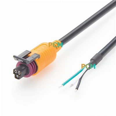
A TE / AMP 1745078-1 compatible high-flex CAN Bus cable assembly is a custom cable designed with a sealed 6-position automotive connector interface on one side and open-end wiring on the other side. The connector interface can be used in CAN Bus cable assemblies when the equipment interface and pinout match the customer's system requirements.
The open-end side provides flexibility for custom termination, such as connecting to an ECU, controller, terminal block, internal harness, sensor module, actuator module or customer-specific connector. The high-flex cable structure makes it suitable for moving applications where a normal static cable may not provide enough bending life.

Figure 1. High-flex CAN Bus cable assembly compatible with TE / AMP 1745078-1

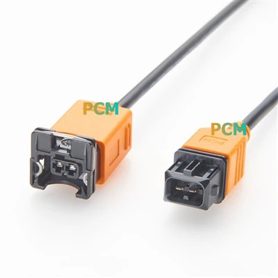
Figure 2. 1745078-1 compatible sealed connector interface for CAN and auxiliary signals
Why Ordinary Static CAN Cables May Fail in Dynamic Applications
A CAN Bus cable that performs well in a fixed installation may not be suitable for drag chain or moving equipment. In dynamic applications, the cable structure must resist repeated bending while maintaining stable electrical performance.
| Potential Issue | Static Cable Risk | High-Flex Cable Design Goal |
|---|---|---|
| Conductor Fatigue | Repeated bending may break or weaken conductors | Use flexible conductor construction for dynamic movement |
| Shield Damage | Shielding may crack or lose continuity | Maintain shielding performance during flexing |
| Signal Instability | CAN communication may become intermittent | Support stable CAN_H / CAN_L transmission |
| Jacket Wear | Outer jacket may be worn by chain movement | Use a jacket suitable for moving cable applications |
Practical note: CAN Bus failures in moving systems are not always caused by the controller or connector. In many cases, cable fatigue, shielding damage, poor strain relief or incorrect dynamic cable selection can also cause communication problems.
CAN Bus Signal Integrity in Moving Cable Systems
For CAN Bus systems, cable reliability is both mechanical and electrical. The cable must maintain stable differential signal transmission while moving inside a drag chain or mobile equipment.
CAN_H and CAN_L are typically transmitted as a differential pair. Cable structure, twisting, shielding, grounding, termination and open-end wiring can all affect communication reliability. For high-flex applications, these factors should be considered together with bending radius and cable movement.
Typical CAN Bus cable considerations include:
- CAN_H and CAN_L pair arrangement
- Characteristic impedance and cable construction
- Shielding and grounding method
- Termination resistor location in the full system
- Open-end pinout and wiring definition
- Cable length and routing inside drag chains
- Final communication test after installation
Role of the TE / AMP 1745078-1 Compatible Connector Interface
The TE / AMP 1745078-1 compatible connector interface can be used as a sealed automotive-style connection point in custom cable assemblies. In CAN Bus applications, the 6-position connector may be assigned for CAN_H, CAN_L, power, ground and auxiliary signals depending on the customer's equipment pinout.
It is important to note that 1745078-1 is a connector housing reference, not a CAN Bus protocol specification. The cable becomes a CAN Bus cable assembly only when the wiring, cable structure and system pinout are designed for CAN communication.
Recommended wording: "Compatible with TE / AMP 1745078-1 for custom CAN Bus cable assemblies" is safer and more accurate than saying "1745078-1 is a CAN Bus connector."
Open-End Wiring for Custom CAN Integration
The open-end design allows the cable to be integrated into different control systems, vehicle wiring layouts or automation equipment. Instead of using a fixed connector on both ends, the open side can be customized according to the customer's wiring drawing or equipment interface.
Typical Open-End Uses
- Connection to ECU or controller terminals
- Connection to PLC or I/O systems
- Connection to customer-specific connectors
- Integration into existing cable harnesses
Common Signal Assignments
- CAN_H
- CAN_L
- Power supply, such as 12V or 24V
- Ground and auxiliary signals
The exact pinout must be confirmed according to the customer's equipment drawing, connector interface or sample cable. A 6-position connector can support different signal assignments depending on the device design.
High-Flex and Drag Chain Cable Design Considerations
A high-flex drag chain CAN Bus cable should be designed for both movement and communication reliability. The design should reduce mechanical stress on conductors, shielding and the connector exit area while supporting stable CAN signal transmission.
Mechanical Design
- High-flex conductor construction
- Drag-chain suitable jacket material
- Proper minimum bending radius
- Strain relief near connector exit
- Abrasion resistance for moving cable paths
Electrical Design
- Stable CAN_H / CAN_L pair structure
- Shielding continuity
- Grounding design
- Open-end termination control
- Final system communication validation

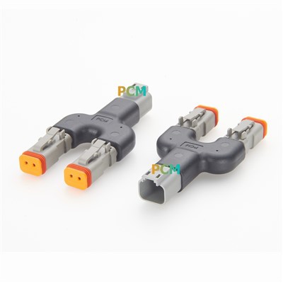
Figure 3. High-flex cable structure for drag chain and moving equipment applications

Figure 4. Open-end wiring side for custom CAN, power and auxiliary signal integration
Typical Applications
This type of high-flex CAN Bus cable assembly is suitable for dynamic and harsh-environment systems where CAN communication, sealed automotive-style connection and custom open-end wiring are required.
Drag Chain Systems
Used in moving cable carriers where the cable must support repeated bending and stable CAN signal transmission.
Industrial Robots and Automation
Suitable for robotic axes, moving automation modules, sensors, actuators and distributed control systems.
Mobile Equipment
Used in construction machinery, agricultural equipment, commercial vehicles, AGV / AMR platforms and other mobile control systems.
Vehicle and Low-Voltage Control Systems
Can be used in custom low-voltage 12V / 24V / 48V vehicle wiring applications when the interface and pinout are confirmed.
Sensor and Actuator Connections
Supports custom CAN communication, power and auxiliary signal wiring for sensors, actuators and control modules.
Replacement and Prototype Harnesses
Useful for prototype development, equipment maintenance, replacement cable projects and small-batch custom wiring.
Product Introduction and Key Features
Premier Cable offers a high-flex drag chain CAN Bus cable assembly compatible with TE / AMP 1745078-1. The cable is designed with a sealed 6-position automotive-style connector interface on one side and open-end wiring on the other side, making it suitable for custom CAN communication, power and auxiliary signal applications.
Unlike standard static CAN cables, this cable is intended for dynamic applications where repeated bending, drag chain movement, vibration and equipment motion may affect long-term cable reliability.
| Product Type | High-Flex Drag Chain CAN Bus Cable Assembly |
| Connector Interface | Compatible with TE / AMP 1745078-1 |
| Connector Type | 6-position sealed automotive-style connector interface |
| Cable Side | Open-end wiring for custom termination |
| Main Signal Use | CAN_H, CAN_L, power, ground and auxiliary signals, depending on pinout |
| Application Type | High-flex, drag chain, dynamic industrial and mobile equipment wiring |
| Customization | Cable length, pinout, open-end stripping, shielding, jacket and labeling support |
Key Features
- Compatible with TE / AMP 1745078-1 connector interface
- High-flex cable design for drag chain applications
- Suitable for CAN Bus signal, power and auxiliary wiring
- Open-end design for custom equipment integration
- Sealed automotive-style connector interface
- Designed for mobile equipment, robots and automation systems
- Custom cable length, pinout and stripping length support
What to Confirm Before Ordering
Before ordering a high-flex CAN Bus cable assembly compatible with TE / AMP 1745078-1, the connector interface, pinout, cable structure and application environment should be confirmed carefully.
Recommended confirmation checklist:
- Connector interface and mating part compatibility
- Required pinout and CAN_H / CAN_L assignment
- Power, ground and auxiliary signal requirements
- Cable length and open-end stripping length
- Drag chain bending radius requirement
- Expected movement frequency or flex cycle requirement
- Shielding and grounding method
- Jacket material and environmental conditions
- Labeling, color coding or custom marking requirements
- Final system communication test requirements
If the customer does not have a drawing, connector photos, equipment model, original cable sample or a pinout table can help confirm the correct cable assembly design.
Conclusion
A high-flex CAN Bus cable assembly for drag chain applications must be designed for both communication reliability and mechanical durability. In moving systems, the cable must maintain stable CAN_H / CAN_L signal transmission while withstanding repeated bending, vibration, jacket wear and connector-side stress.
A TE / AMP 1745078-1 compatible sealed connector interface with open-end wiring provides flexibility for custom CAN Bus, power, ground and auxiliary signal integration, especially in automation equipment, mobile machinery, industrial robots, vehicle control systems and drag chain applications.
For custom projects, customers should confirm:
- Connector interface
- Pinout and signal assignment
- High-flex and drag chain requirements
- Shielding and grounding structure
- Cable length and open-end termination
- Final equipment communication test requirements
With proper cable design and system confirmation, a high-flex CAN Bus cable compatible with TE / AMP 1745078-1 can provide a reliable connection solution for demanding dynamic control applications.
📩 Contact Premier Cable
- ✅ OEM & ODM support
- ✅ Factory-direct wholesale pricing
- ✅ 100% Tested for continuity and insulation
- ✅ Free engineering samples and rapid prototyping