41-924-300 Compatible Cable: PCIe-to-PXI Remote Control Interface Guide
Understand how the 3 m high-speed interface cable links a host PC to a PXI chassis, why a standard CX4 or InfiniBand cable is not automatically interchangeable, and what engineers and buyers should verify before ordering a compatible replacement.
Quick answer: The 41-924-300 is a 3 m high-speed expansion cable used in the 41-924 PCIe-to-PXI remote control system. It connects the 51-924-001 PCIe interface card in a host computer to the 41-924-001 interface module installed in the system controller slot of a PXI chassis.
Important compatibility note: Do not select a replacement only because the connector resembles a CX4, InfiniBand 4X or external PCIe cable. Mechanical mating does not confirm the required pair mapping, polarity, sideband wiring, shielding, signal integrity or functional compatibility.
📋 Contents
What Is the 41-924-300 PCIe-to-PXI Cable?
The 41-924-300 is a 3 m PXI remote control interface cable for the Pickering 41-924 system. It is described as a high-speed expansion cable for the PCIe-to-PXI remote control interface and is supplied as the standard cable length in the 41-924-001-KIT.
The cable forms the external physical link between a 51-924-001 PCIe interface card installed in the host PC and a 41-924-001 PXI interface module installed in Slot 1, the system controller slot, of a PXI chassis. It does not replace either interface card and is not an Ethernet, USB or camera-control cable.

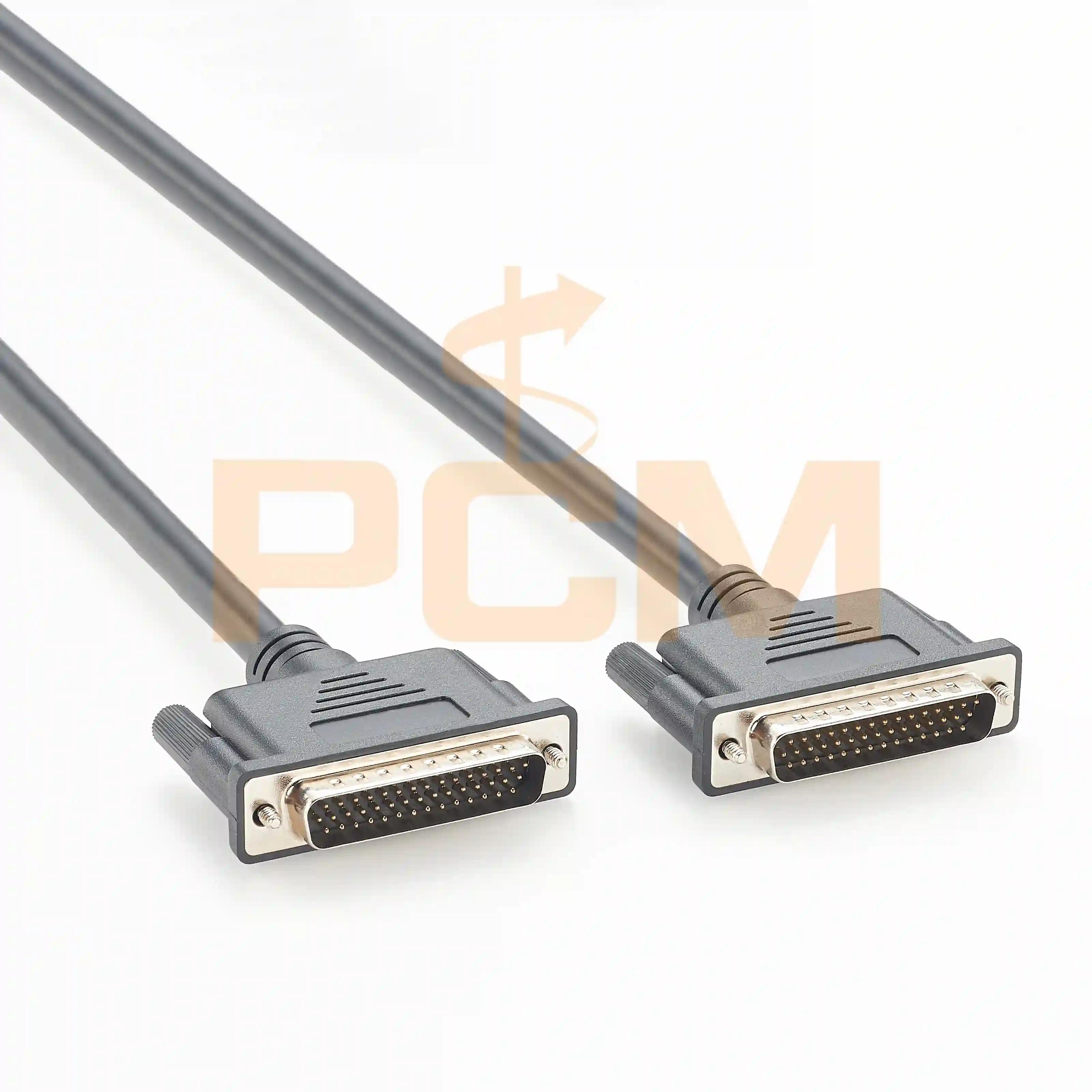
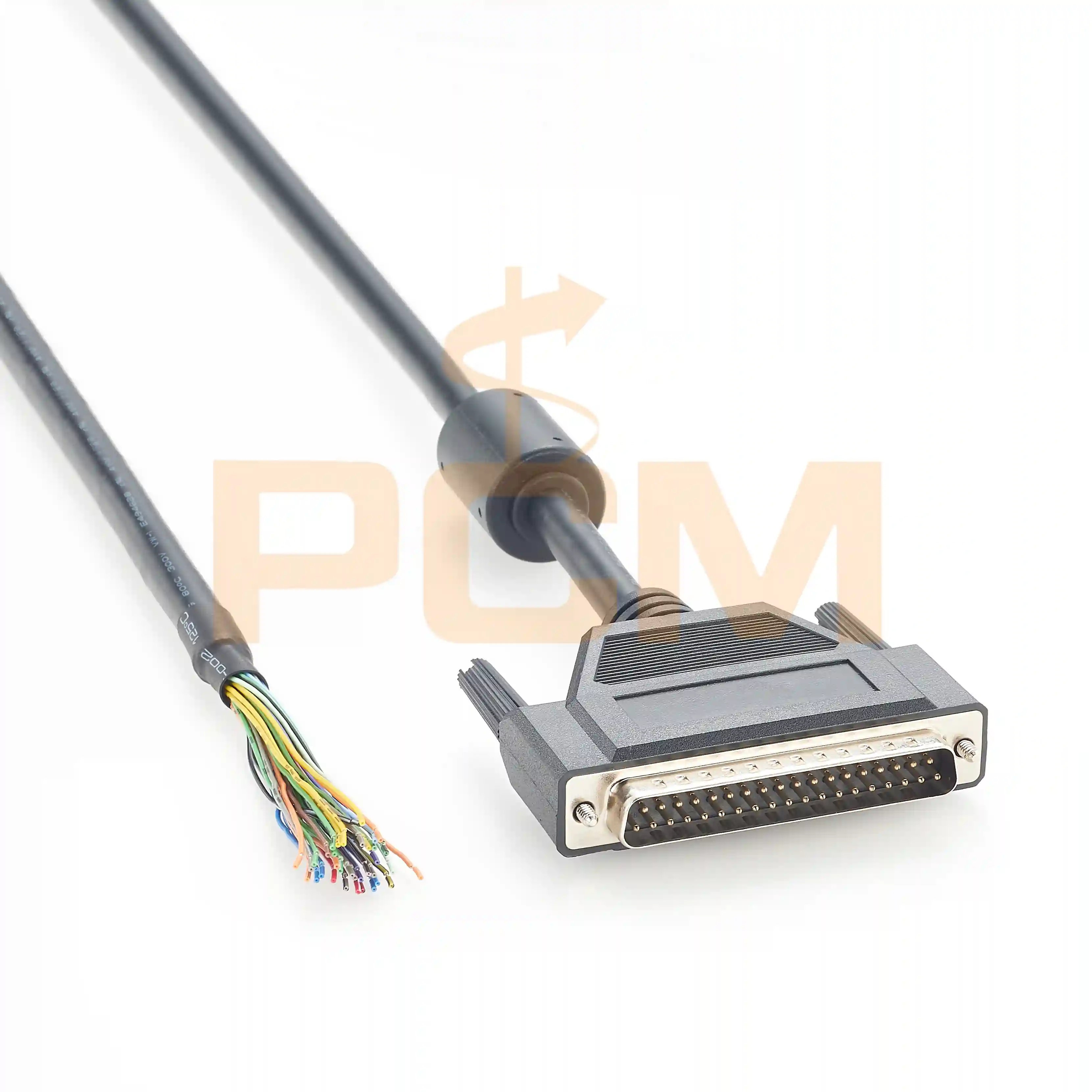
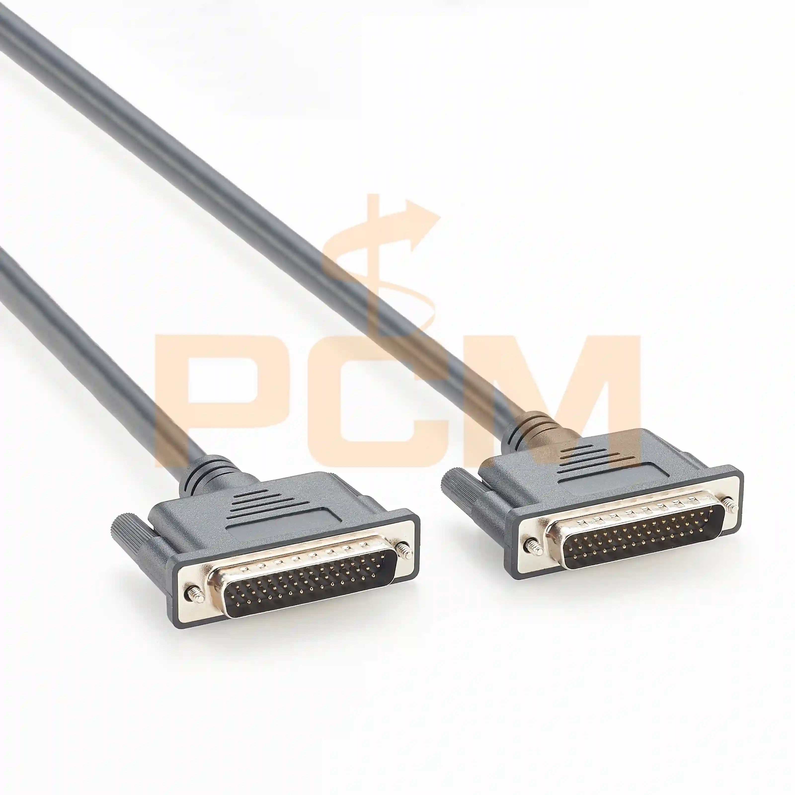
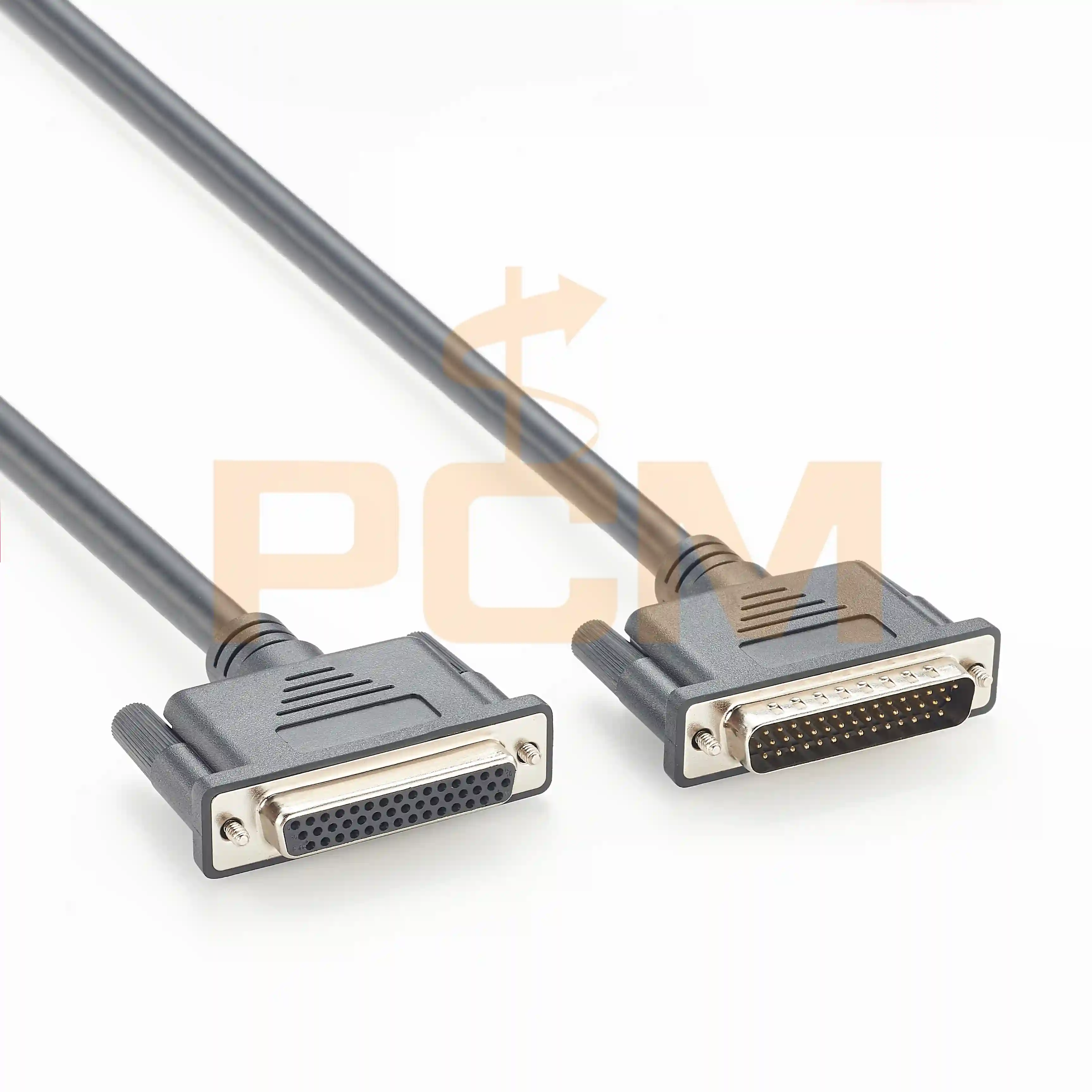
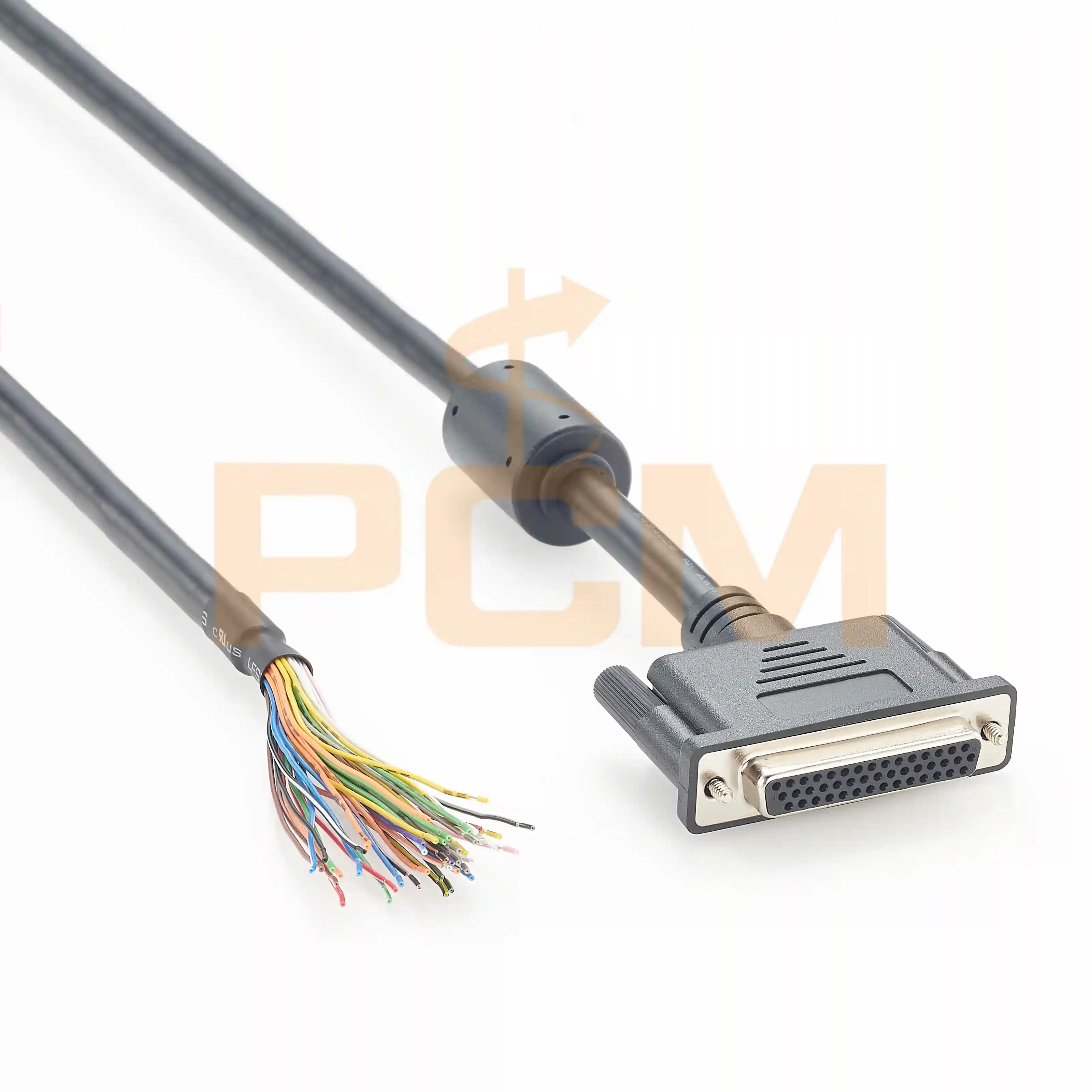
41-924-300 Compatible Cable Assembly

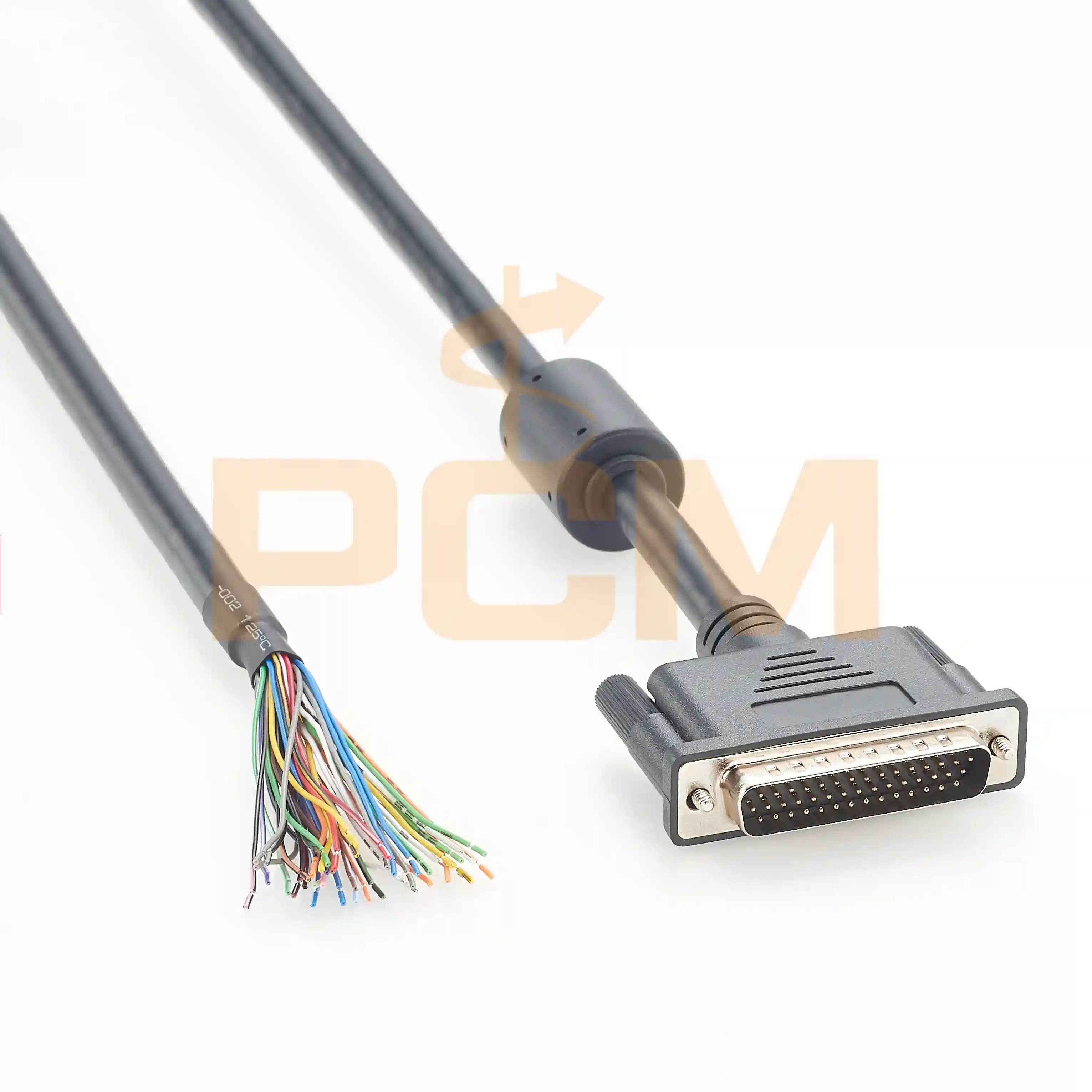
High-Speed Screw-Lock Connector
Key distinction: "41-924-300" identifies a specific cable application and 3 m length. "CX4" or "InfiniBand 4X" describes a connector and cable form commonly associated with other high-speed systems. The names should not be treated as equivalent specifications.
How the PCIe-to-PXI Remote Control System Works
The 41-924 system extends a PCI Express connection from a host computer to a separate PXI chassis. The host card and PXI module bridge the two backplanes, while the external interface cable carries the high-speed differential link between them.

application
PCIe Host Link
The system uses a single-lane PCI Express link. Official documentation lists an effective signaling rate of up to 2.5 Gbit/s and describes the external channel as dual-simplex, using separate transmit and receive differential pairs.
Transparent PXI Expansion
The PCIe-to-PCI bridge presents hardware in the remote PXI chassis to the host system. The system documentation states that additional software is not required on the external chassis for the bridge itself.
Shielded External Cable
The interface depends on shielded twisted-pair construction, controlled pair routing and secure connector retention. These characteristics are essential for preserving signal integrity across the external link.
41-924-300 Compatibility at a Glance
The following table summarizes the published system requirements most relevant to cable selection. It should be used together with the target equipment model, original cable reference and an approved cable drawing.
| Compatibility Item | Published Requirement or Selection Note |
|---|---|
| Reference part number | 41-924-300 |
| Nominal cable length | 3 m |
| Host-side hardware | 51-924-001 PCIe remote control interface card |
| Chassis-side hardware | 41-924-001 PXI remote control interface module |
| Host link | Single-lane PCI Express connection |
| Published signaling rate | Up to 2.5 Gbit/s |
| PXI bus support | 32-bit / 33 MHz full data throughput |
| PXI chassis installation | 41-924-001 installed in the PXI system controller slot, Slot 1 |
| PXIe controller slot | The published datasheet states that 41-924-001 is not suitable for PXIe controller slots |
| Maximum published distance | Up to 7 m using the specified high-quality shielded twisted-pair cable system |
| Retention | Screw-lock connection; retention screws should be firmly tightened |
PXI versus PXIe: This article concerns the 41-924 PCIe-to-PXI system. Do not advertise the cable as a general PCIe-to-PXI/PXIe cable unless compatibility with the specific PXIe remote-control hardware has been independently confirmed.
Is a Standard CX4 or InfiniBand Cable Compatible with 41-924-300?
Not automatically. A cable may use a connector body that looks like a CX4 or InfiniBand 4X assembly and still be electrically unsuitable for the 41-924 interface. The connector shell is only one part of the complete interconnect.
CX4-style cable assemblies have been used for InfiniBand, 10 Gigabit Ethernet, machine vision, HS-Link, Camera Link HS and external PCIe applications. These systems can require different contact assignments, active lane usage, polarity conventions, sideband signals and shielding termination. A cable that physically plugs in can therefore fail to establish a link or may operate intermittently.
| Comparison Factor | Generic CX4 / InfiniBand Cable | 41-924-300 Compatible Configuration |
|---|---|---|
| Connector appearance | May appear mechanically similar | Must mate correctly with 51-924-001 and 41-924-001 |
| Signal assignment | Defined by the original network, imaging or proprietary application | Must match the 41-924 remote-control interface requirements |
| Differential pairs | Lane count and routing vary by application | Transmit and receive pair mapping and polarity must be verified |
| Length | Many standard and custom lengths may exist | 41-924-300 is specifically the 3 m version |
| Performance proof | May be qualified for another protocol | Should be validated for continuity, pair assignment, shielding and target-system operation |
Engineering takeaway: Connector similarity can justify using the same manufacturing platform, tooling and shielded cable architecture. It cannot, by itself, justify a compatibility claim.
41-924-100 vs. 41-924-300 vs. 41-924-700
The three published accessory references identify the cable length. Selecting the shortest practical cable generally simplifies routing and reduces unnecessary cable exposure, but the installation must still provide adequate service clearance and bend radius.
| Part Number | Published Length | Typical Selection Scenario | Procurement Note |
|---|---|---|---|
| 41-924-100 | 1 m | PC and PXI chassis installed close together | Confirm that rack service loops and connector access remain adequate |
| 41-924-300 | 3 m | Standard kit cable and general test-system installation | Use this reference when replacing the standard 3 m assembly |
| 41-924-700 | 7 m | Greater separation between host PC and PXI chassis | 7 m is the maximum published connection distance for this system |
Custom-length caution: A cable can be manufactured to a requested mechanical length, but reliable PCIe operation should not be assumed outside the published 1 m, 3 m and 7 m options. Any non-standard length requires application-specific signal-integrity and functional validation.
What Must Be Verified in a 41-924-300 Replacement Cable?
A credible replacement program should define the complete cable assembly rather than relying on connector photographs alone. The following checks are relevant to engineering approval, incoming inspection and finished-cable testing.
Connector and Retention Hardware
Confirm connector shell dimensions, keying, mating orientation, screw spacing, retention-screw thread and backshell clearance at both equipment panels.
Pin-to-Pin Wiring
Approve a controlled wiring table. Verify each contact, unused position, ground connection and sideband circuit. Do not assume that a generic straight-through CX4 pinout is correct.
Differential-Pair Routing
Maintain pair integrity through the cable and connector termination. Verify transmit/receive assignment, positive/negative polarity, pair-to-pair consistency and minimized untwist length.
Shield Termination
Confirm pair shielding, overall foil or braid construction, drain-wire routing and low-impedance shell bonding. Shield continuity should be included in the inspection plan.
Mechanical Construction
Define overall length, tolerance, cable outside diameter, minimum bend radius, strain relief, jacket material, label location and packaging requirements.
Finished-Cable Validation
Perform continuity, open, short, miswire, polarity and shield-continuity tests. For the strongest compatibility evidence, complete a functional link test with the target 51-924-001 and 41-924-001 hardware.
PCM-S-0610 Cable Construction and 41-924-300 Configuration
Premier Cable PCM-S-0610 uses screw-lock InfiniBand 4X / CX4-style connectors and a multi-pair shielded cable construction. The existing product platform is also used for HS-Link and Camera Link HS cable assemblies. For a 41-924-300 application, the assembly must be supplied in the confirmed PCIe-to-PXI wiring configuration rather than treated as a generic machine-vision cable.
The published PCM-S-0610 page lists eight 28 AWG shielded pair groups, overall foil and braid shielding, a nominal 9.6 mm cable outside diameter and OEM cable-length capability.
| Specification | PCM-S-0610 Platform / 41-924-300 Ordering Configuration |
|---|---|
| Premier Cable part number | PCM-S-0610 |
| Product type | High-speed shielded cable assembly with screw-lock CX4 / InfiniBand 4X-style connectors |
| Connector configuration | Male-to-male; mating dimensions and retention hardware to be confirmed against target equipment |
| Published cable OD | 9.6 mm nominal |
| Published cable construction | Eight 28 AWG shielded-pair groups with overall foil and braid shielding |
| 41-924-300 length | 3 m configuration |
| Required wiring | Confirmed 41-924 application-specific pair and contact mapping; not generic HS-Link or InfiniBand wiring |
| Available customization | Length, label, packaging and application-specific wiring subject to engineering confirmation |
| Recommended production tests | Continuity, open/short, miswire, pair polarity, shield continuity, mechanical inspection and functional system validation where available |

PCM-S-0610

PCM-S-0610
Installation and Power-Up Sequence
The cable is part of a PCIe bridge system, so connection and power sequencing matter. The official user manual instructs users to secure both cable ends before power-up and warns against disconnecting the interface cable while the system is operating.
- Turn off the host PC and PXI chassis before connecting the cable.
- Connect one end to the 51-924-001 interface card in the host PC.
- Tighten the cable retention screws firmly.
- Connect the other end to the 41-924-001 module in PXI Slot 1.
- Check that both connectors are fully seated and the cable is routed without excessive bending or tension.
- Confirm the interface cable is connected and secured.
- Power on the PXI chassis first.
- Power on the host PC second so that the BIOS can identify devices behind the PCI bridge and assign resources during startup.
- Shut down and power off the host PC first.
- Power off the PXI chassis second.
- Disconnect the cable only after both systems are fully powered down.
Do not hot-unplug the cable: Disconnecting the interface cable after the host PC and PXI chassis are powered can cause system errors, data loss, a system hang or a crash. If an improper disconnection occurs, reconnect the cable and reboot both systems in the correct sequence.
When Should the 41-924-300 Cable Be Inspected or Replaced?
A failed chassis connection is not always caused by the cable, but the cable should be inspected whenever the link becomes intermittent, equipment has been moved or the connectors show physical damage.
Cable-Related Warning Signs
- Damaged or missing retention screws
- Bent metal shell or damaged mating face
- Cracked backshell or separated strain relief
- Severe kinks, crushing or repeated tight bends
- Intermittent system detection when the cable is moved
- Open, short, miswire or shield-continuity failure
Other Causes to Check
- Incorrect PXI module slot
- PXI chassis powered after the host PC
- Loose connector retention screws
- Fault in the 51-924-001 PCIe card
- Fault in the 41-924-001 PXI module
- BIOS resource-allocation issue
- Chassis power or backplane problem
Information for a Replacement Quote
- Original reference: 41-924-300
- Required length and quantity
- Target card and module model numbers
- Clear photographs of both equipment ports
- Original cable photographs and label
- Wiring drawing or sample when available
- Required electrical and functional tests
Diagnostic practice: Record the power-up sequence, LED status and whether the problem follows the cable when a known-good assembly is substituted. This helps separate cable faults from host-card, PXI-module, chassis or BIOS issues.
Frequently Asked Questions
What is the 41-924-300 cable?
It is the 3 m high-speed interface cable used in the 41-924 PCIe-to-PXI remote control system. It connects the 51-924-001 PCIe host card to the 41-924-001 PXI interface module.
Is 41-924-300 a standard InfiniBand CX4 cable?
It may use a mechanically similar high-density screw-lock connector and shielded multi-pair cable structure, but a standard InfiniBand cable should not be assumed compatible. The complete pin mapping, pair routing, polarity, sideband wiring and signal performance must match the 41-924 application.
What equipment does the 41-924-300 connect?
It connects the 51-924-001 PCIe interface card installed in a host computer to the 41-924-001 interface module installed in the system controller slot of a PXI chassis.
Can the 41-924-001 module be installed in a PXIe controller slot?
The current 41-924 datasheet states that the 41-924-001 is intended for a PXI chassis controller slot and is not suitable for PXIe controller slots. Confirm the chassis type before ordering the cable or interface kit.
What is the maximum cable length for the 41-924 system?
The published maximum connection distance is 7 m. The listed accessory references are 41-924-100 for 1 m, 41-924-300 for 3 m and 41-924-700 for 7 m.
Can the cable be connected or disconnected while powered?
No. The interface cable should be fully connected before power-up and should not be disconnected while the host PC and PXI chassis are operating. Improper disconnection can cause system errors, data loss or a system crash.
What is the correct power-up sequence?
Connect and secure the cable, power on the PXI chassis first, and then power on the host PC. For shutdown, power off the host PC before powering off the PXI chassis.
Can a custom 41-924-300 replacement be manufactured?
Yes, subject to confirmation of the connector interface, cable length, contact mapping, differential-pair routing, shielding and test requirements. A sample or approved wiring drawing is recommended when the original electrical specification is unavailable.
What tests should be requested for a compatible replacement?
At minimum, request continuity, open/short, miswire, pair-polarity and shield-continuity testing. Functional validation with the target host card and PXI module provides stronger compatibility evidence than a continuity test alone.
Sources Used for This Guide
Need a 41-924-300 Compatible PCIe-to-PXI Cable?
Send the original part number, required cable length, quantity and the model numbers of the host PCIe card and PXI interface module. For non-standard or legacy systems, include clear connector photographs, the original cable label, an approved pinout or an original sample.
Premier Cable supports high-speed shielded cable assemblies with application-specific wiring, custom labeling, packaging and finished-cable electrical testing. Functional system validation should be specified when required.