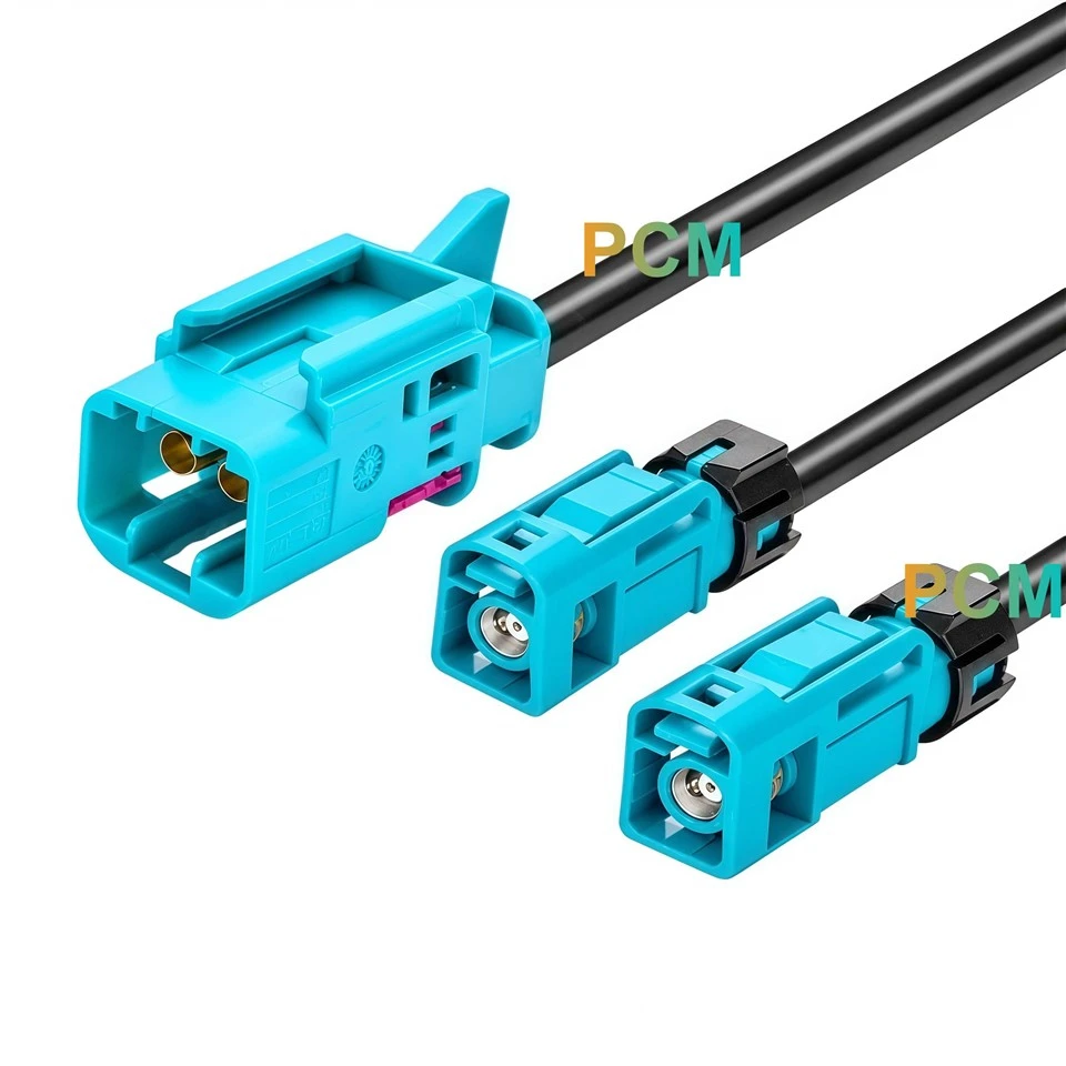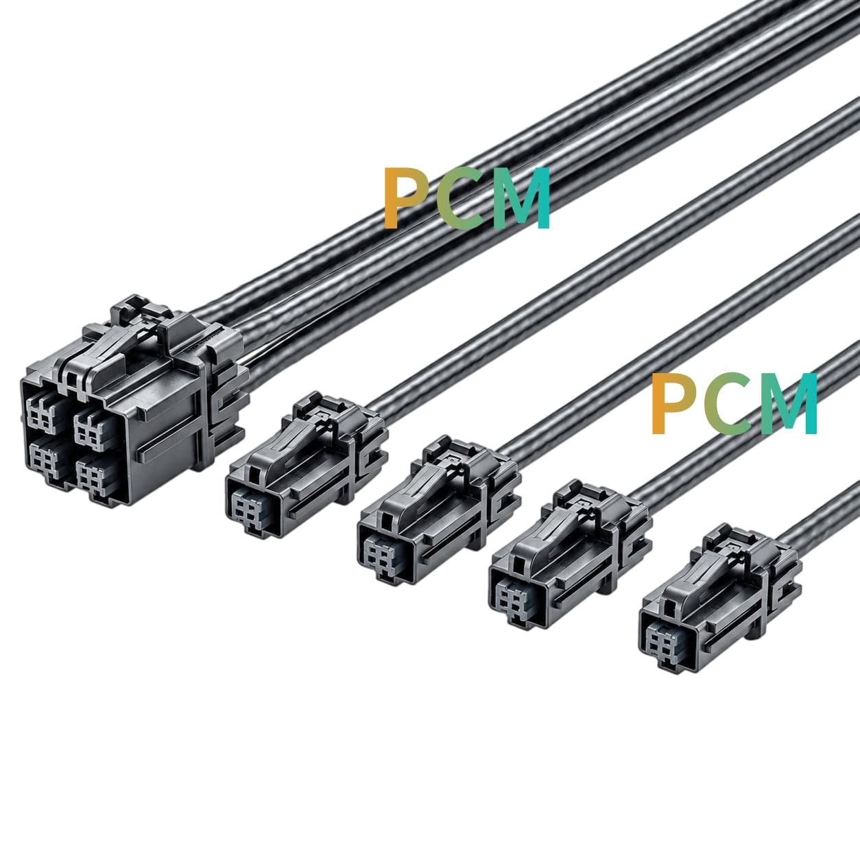
01
Product Display
|
|
|
|
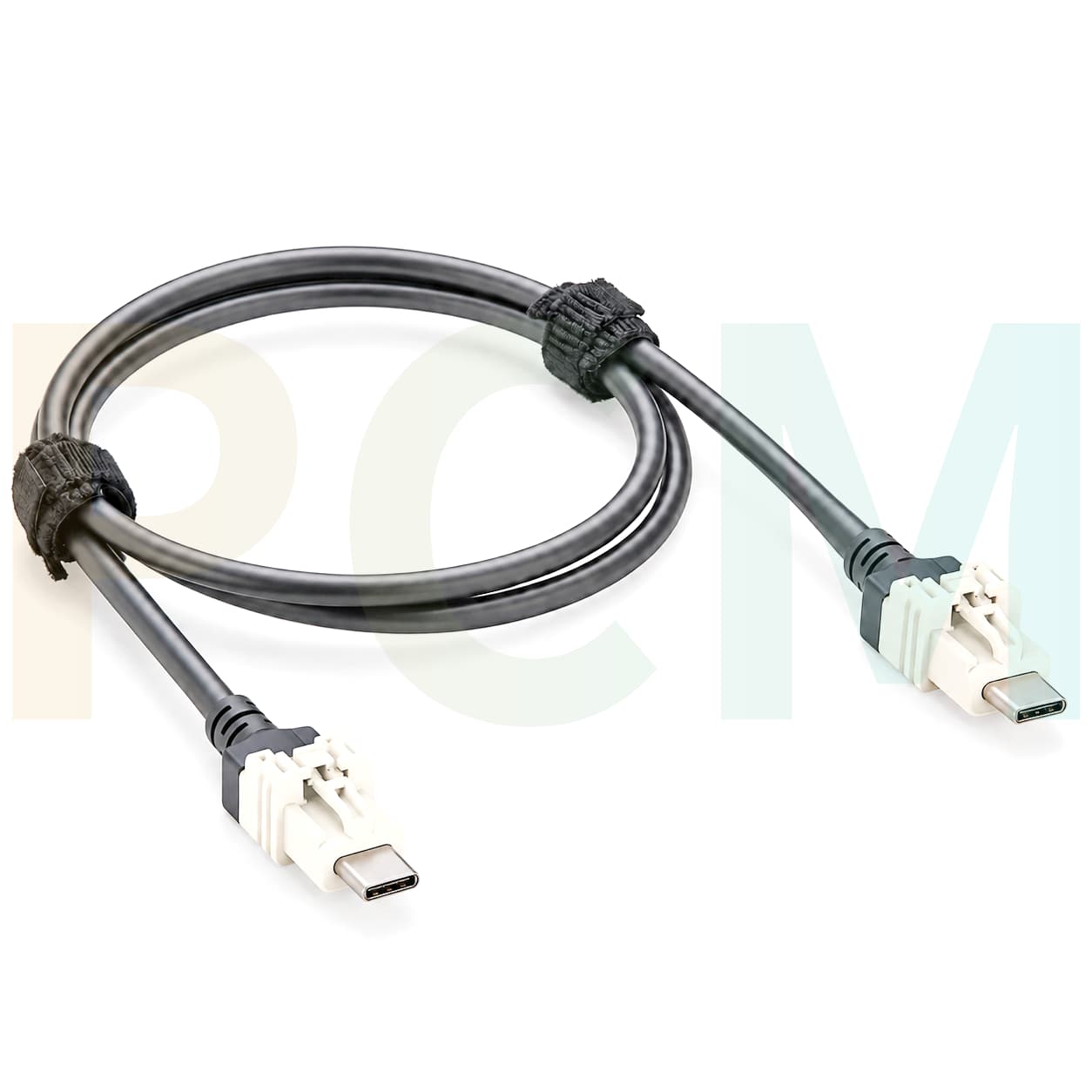
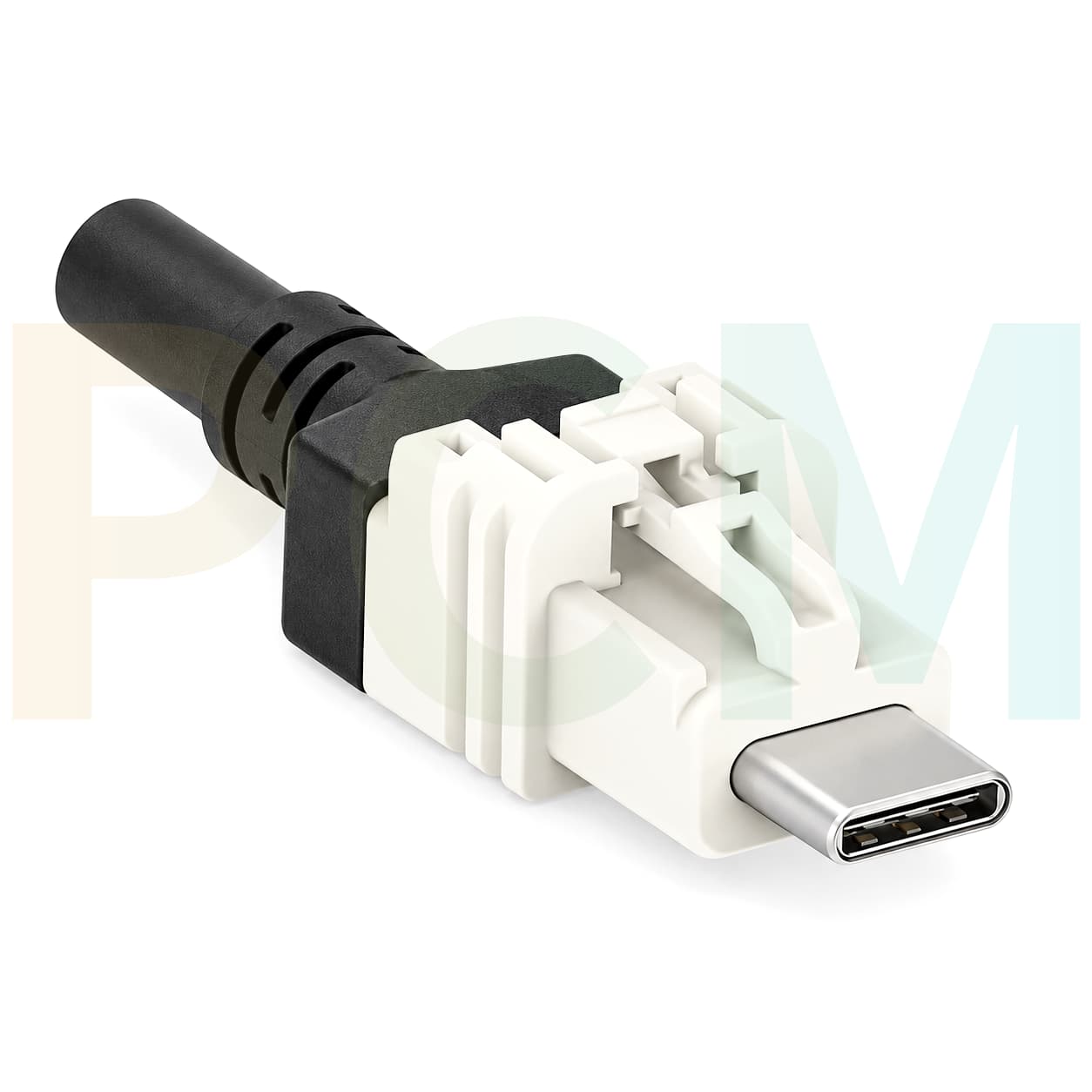
What Is This Product ?
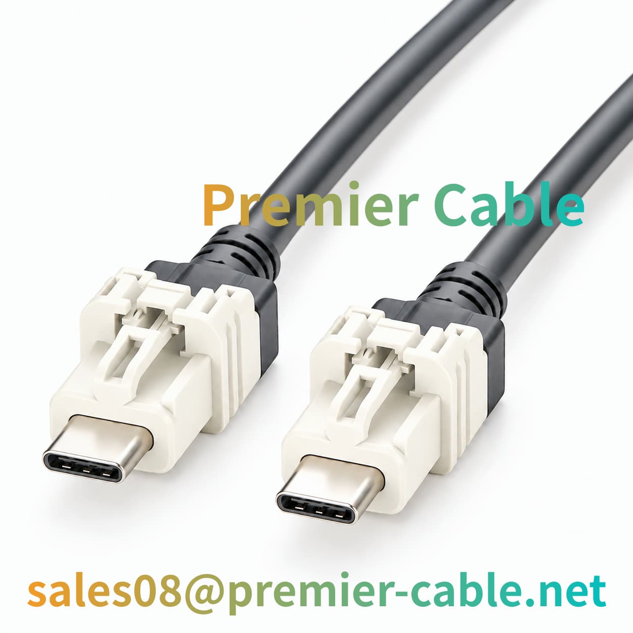
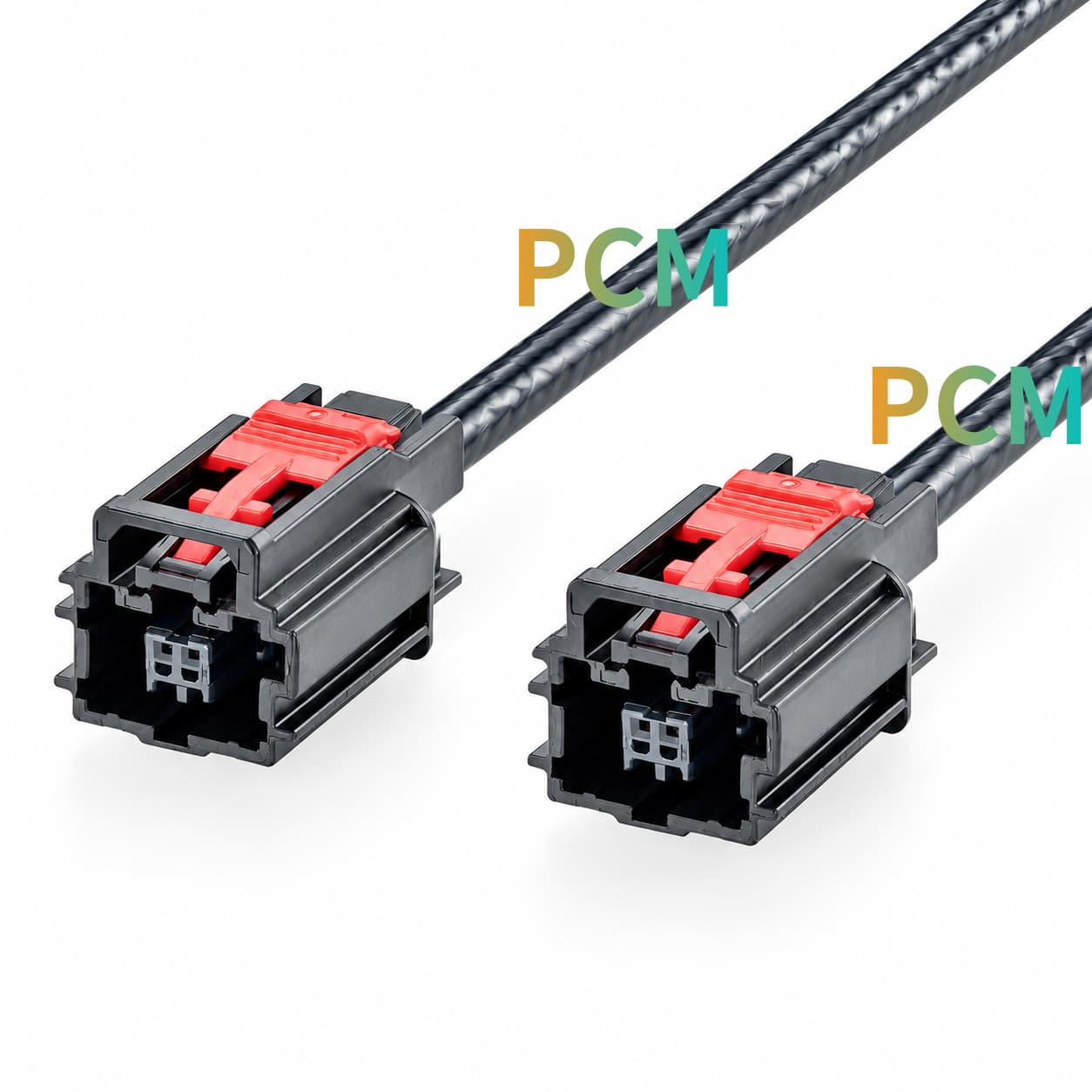
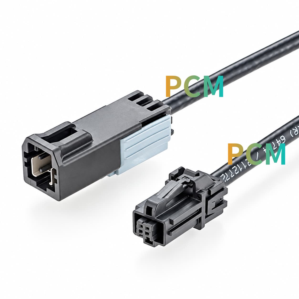
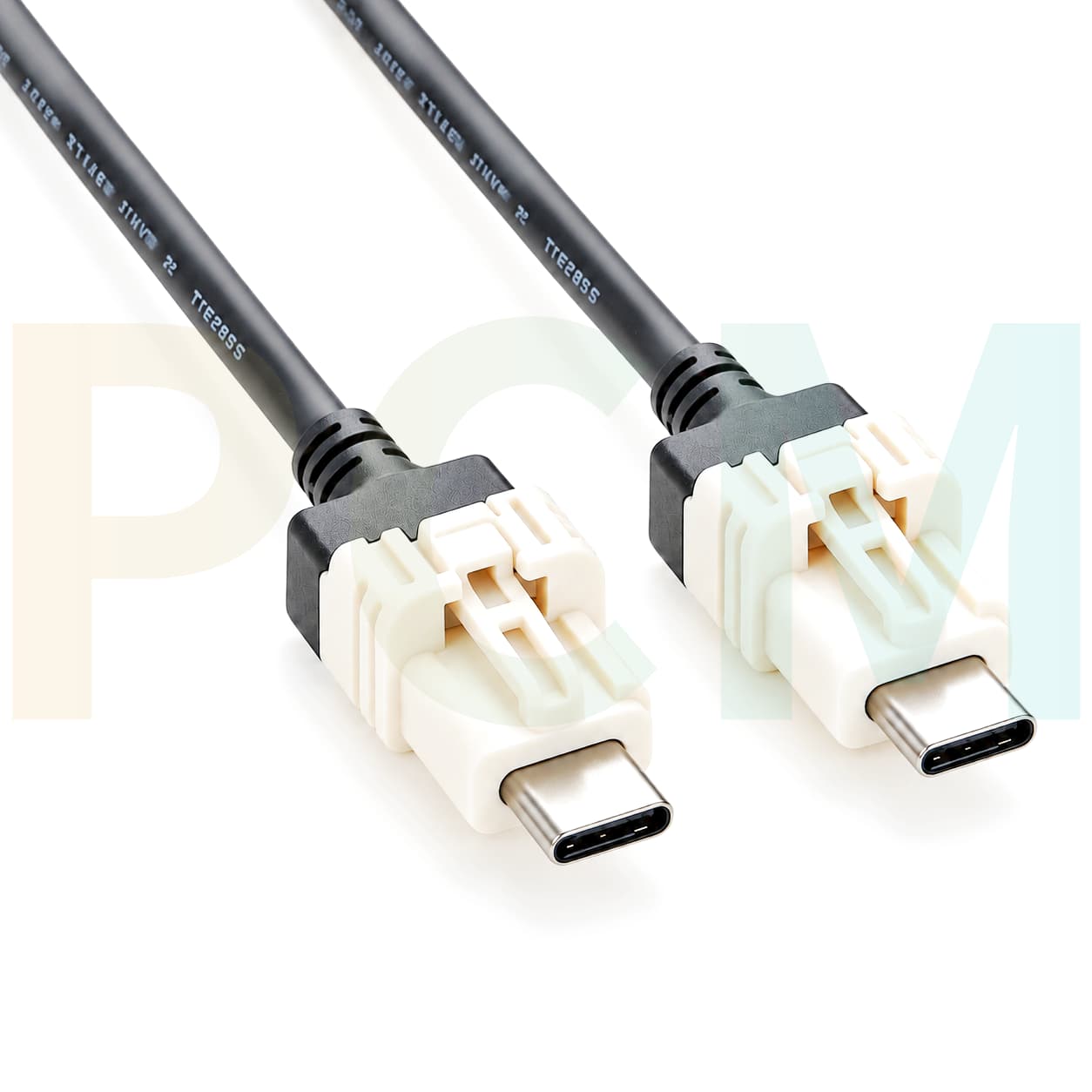
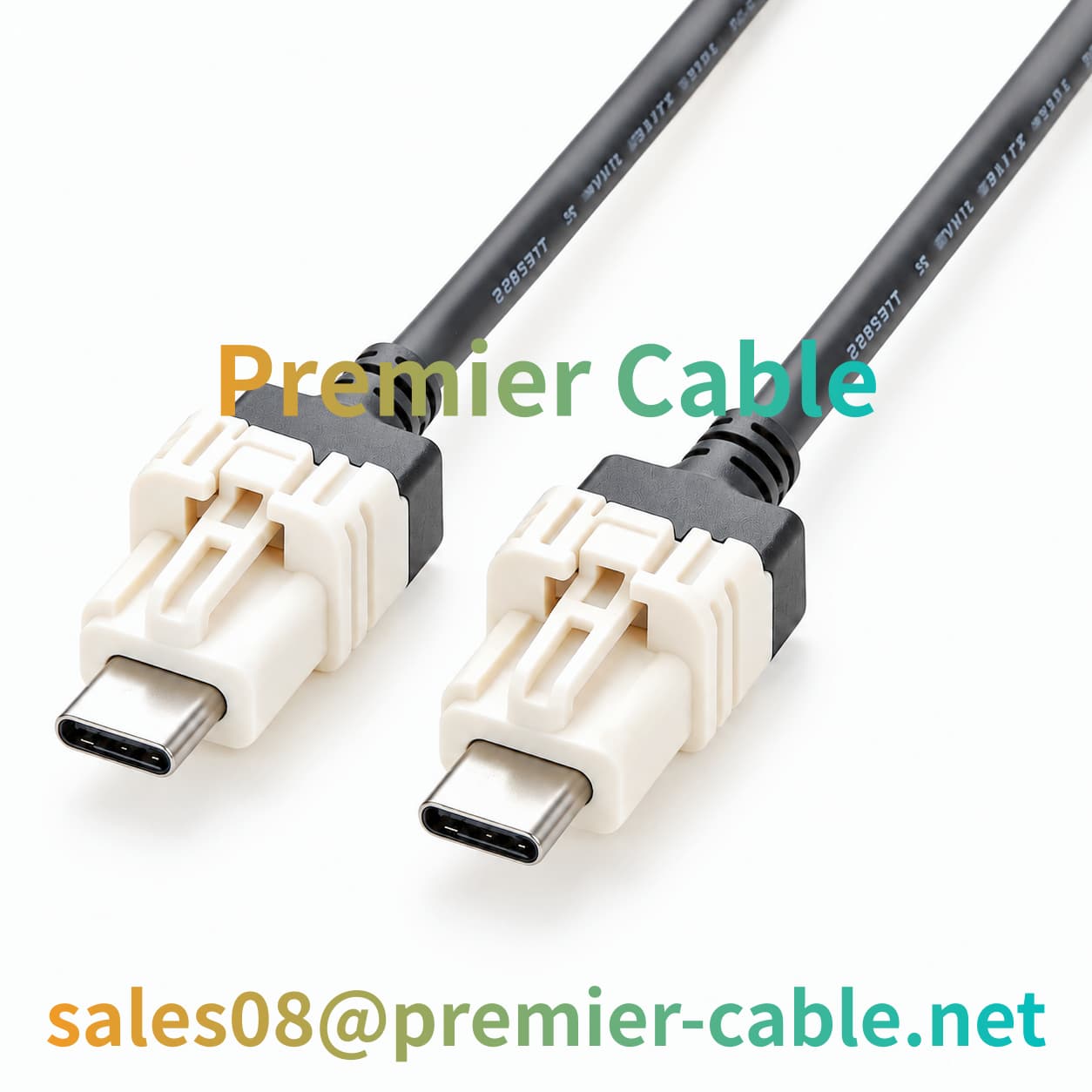
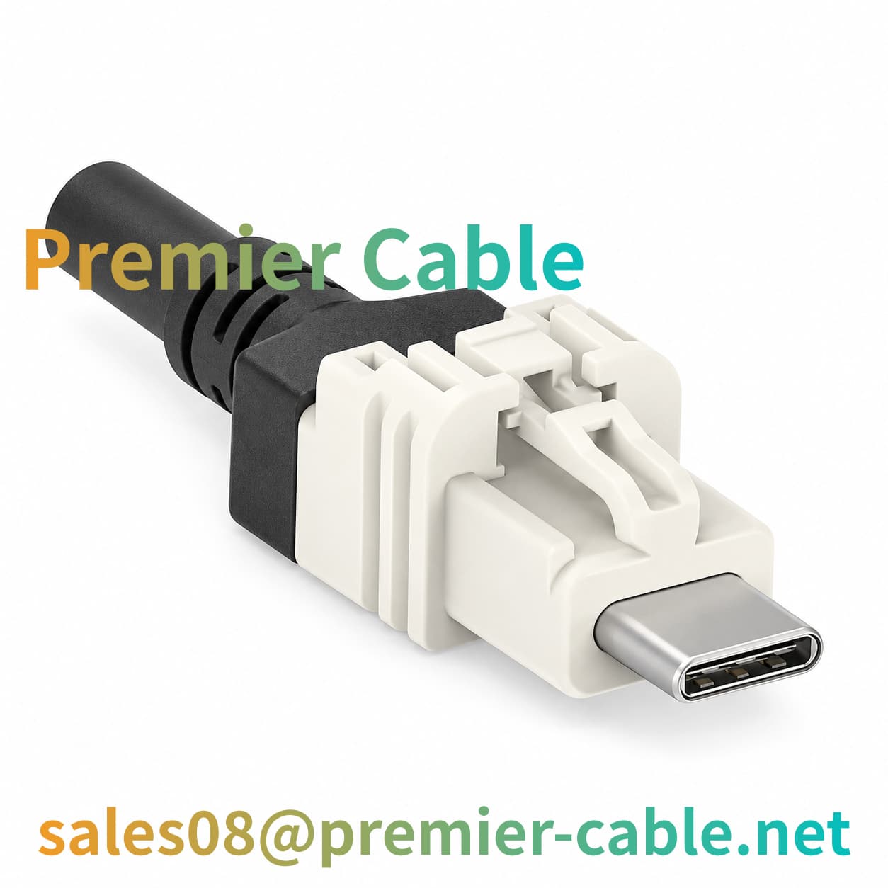
The TE Connectivity 2398010-2 automotive-grade USB-C cable is a dual-ended cable assembly developed by Premier Cable based on the TE 2398010-2 B-coded connector. Both ends feature white connector housings and male USB Type-C interfaces, combined with black cables and stress-relief structures at the connector rear.
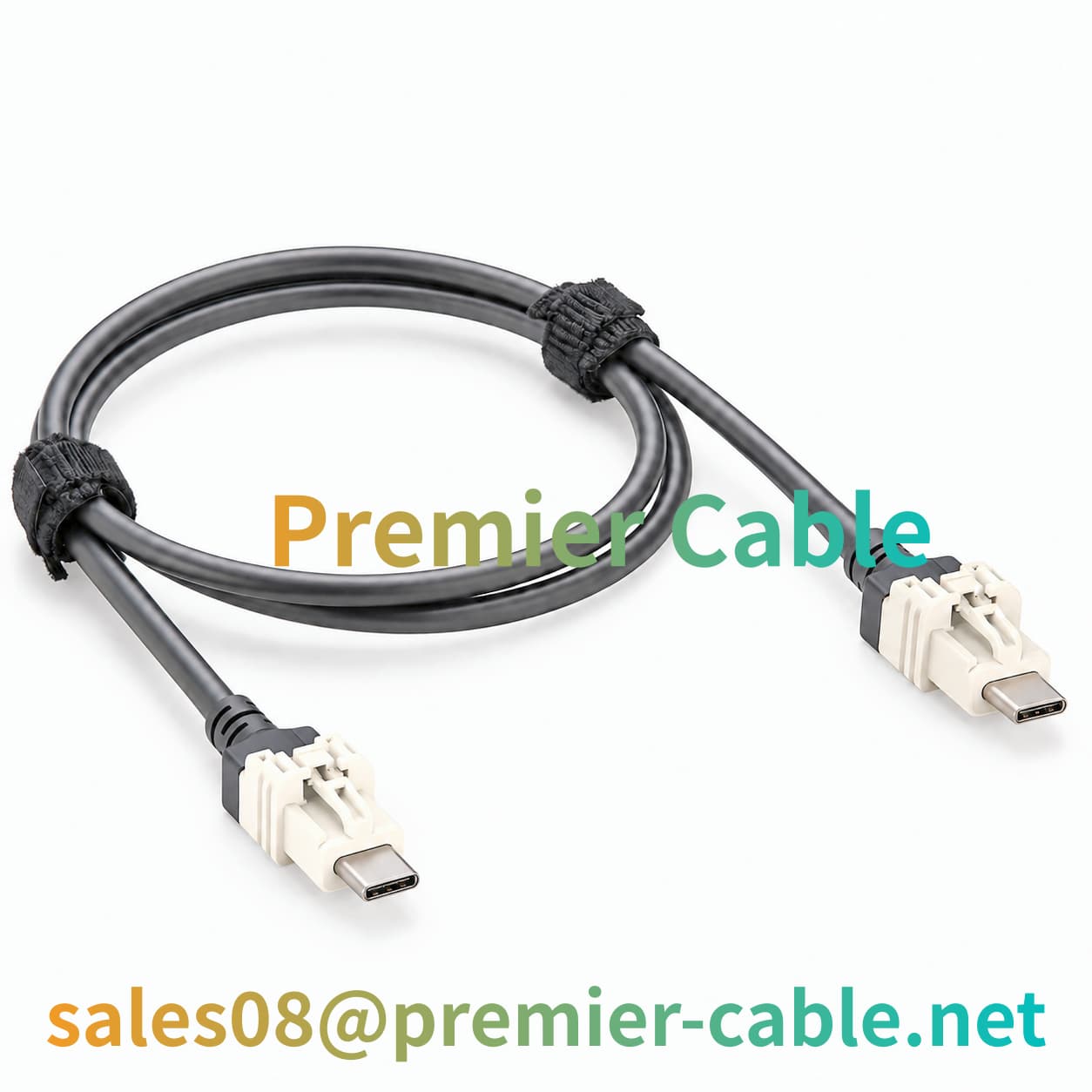
Compared to purchasing connectors separately, this pre-assembled cable assembly integrates both end connectors with the cable into a single product, helping customers manage material configurations uniformly during sample development, equipment assembly, and harness procurement.
What Does This Product Do ?
The pre-assembled USB-C cable assembly is developed based on the TE 2398010-2 connector, designed to meet the interconnection and integration requirements of specific B-coded interfaces in automotive electronic projects. When the matching interfaces, USB host/slave roles, pin mappings, and internal circuit designs of both end devices comply with the specifications, it can be used to connect compatible in-vehicle infotainment systems, electronic control units (ECUs), development equipment, and test platforms.
By integrating the specified connector with a well-defined finished cable configuration, this solution helps standardize material lists, wiring definitions, assembly, and inspection requirements, reducing configuration uncertainties during prototype development and mass production, and facilitating engineering reviews and sample validation.
What Are the Benefits of Using This Product ?
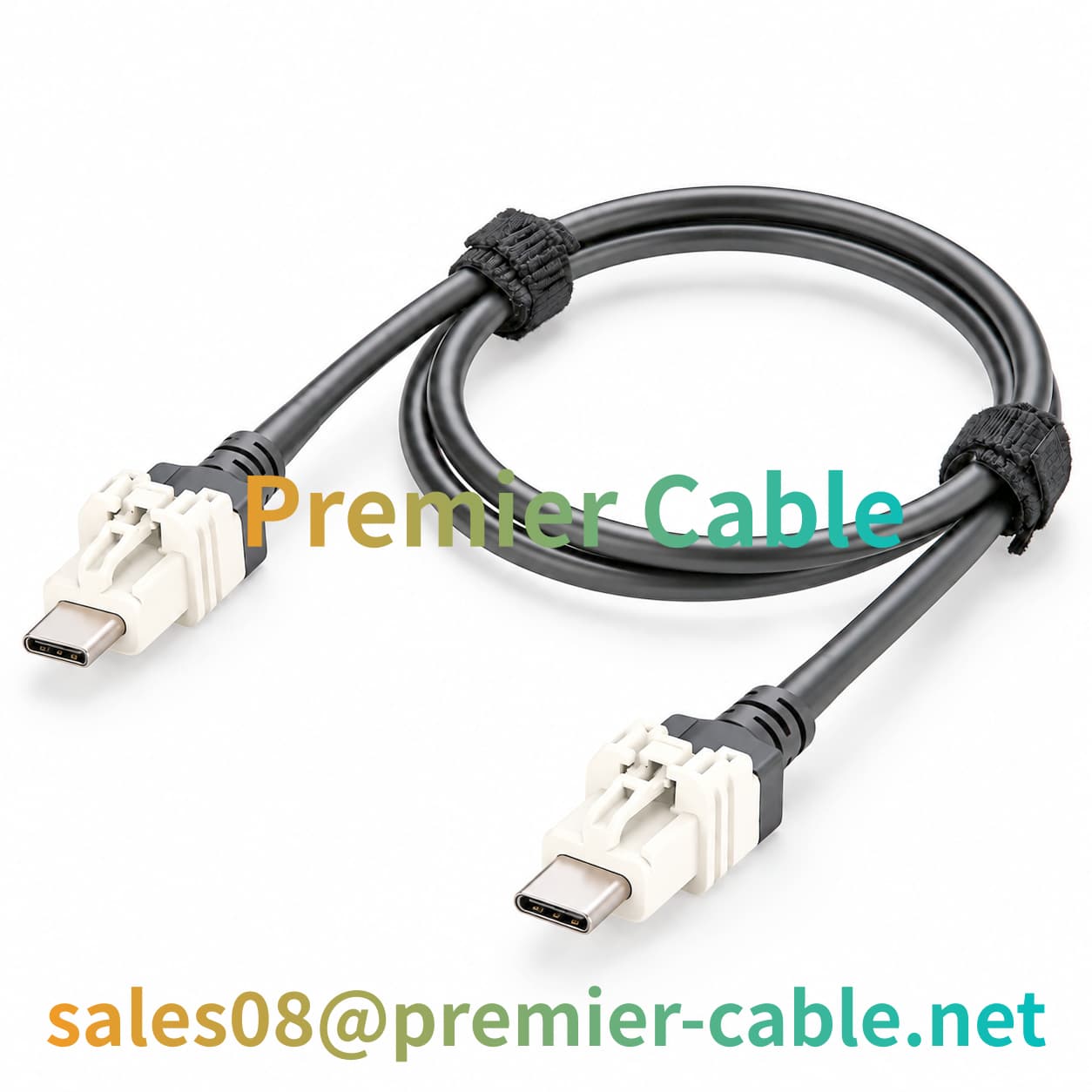
For automotive electronics manufacturers and harness integrators, a pre-assembled dual-ended cable can reduce the need to handle connector and cable termination separately on-site. It also establishes a standardized product configuration for sample evaluation, design changes, and repeat purchasing.
Project teams can manage cable length, wiring drawings, inspection items, and order specifications against the complete assembly configuration, reducing confusion between development batches. For long-term procurement, retaining approved drawings and inspection records can improve traceability across subsequent orders.
Product Pain Point Analysis
Interface Identification and Complete-Cable Validation
Automotive USB-C connectors with similar appearances may differ in mechanical coding, mating structures, and terminal assignments. Engineers should verify the intended interface against official TE Connectivity 2398010-2 drawings.
The connector's USB specification alone does not establish finished-cable performance; cable construction, termination quality, wiring configuration, and complete-channel performance still require validation. Defining interface and test requirements early helps reduce mating errors and integration risks.
Procurement and Production Management
Sourcing connectors and cable separately requires coordination of termination methods, wiring assignments, and assembly requirements. Subsequent changes to connector models, cable lengths, or internal wiring can also create batch differences if documentation is not updated.
Using a clearly specified, pre-assembled dual-ended cable and maintaining controlled bills of materials, approved drawings, change records, and inspection records helps simplify prototype development and repeat procurement while improving production consistency and traceability.
Product Knowledge
Why Does Cable Routing Matter in Automotive USB-C Applications ?
Inside automotive electronic equipment, cables typically need to pass through narrow installation spaces and navigate around brackets, housings, and other wiring harnesses. If cables are excessively bent, subjected to continuous tension, or compressed during installation, it may increase mechanical stress on the conductors, shielding structures, and connector terminations.
For automotive-grade USB-C finished cables using the TE Connectivity 2398010-2 connector, it is recommended to determine the cable exit direction, allowable bending radius, mounting positions, and installation clearance around the connector during the design phase.
Proper cable routing not only helps improve assembly neatness but also reduces additional mechanical stress on connectors. For projects requiring mass production, it is recommended to validate cable paths through sample installations and incorporate key wiring requirements into assembly instruction documents.
What Should Be Verified Before Using a USB-C Cable in an Automotive Environment ?
Automotive electronic applications may involve temperature variations, continuous vibration, restricted installation spaces, and different mounting conditions. A connector's inclusion in an automotive electronics product family, or the use of the term "Automotive Grade" in a product name, does not by itself establish that the complete cable assembly meets specific automotive environmental requirements.
For a dual-ended TE Connectivity 2398010-2 USB-C cable, define the operating temperature range, vibration requirements, cable retention method, connector retention requirements, and any exposure to moisture or other environmental factors based on the actual installation location. If the cable is installed in an area subject to significant vibration or temperature changes, establish an appropriate validation plan according to project requirements.
It is also important to distinguish connector specifications from the environmental performance of the complete cable assembly. Connector documentation does not automatically replace environmental test reports for the finished cable.
How to Select the Right Product ?
Step 1: Confirm the Complete Connector Part Number
First, confirm whether the required connector is TE Connectivity 2398010-2 and verify its B coding, vertical male construction, and corresponding mechanical drawing. Do not select a replacement based solely on the USB-C form factor, connector color, or product name.
Step 2: Verify Both Mating Interfaces
Identify the equipment connected at each end of the cable and check the mechanical construction, coding, and pin assignments of the mating interfaces. For equipment using dedicated automotive connector structures, verify mating compatibility using official drawings and interface documentation.
Step 3: Define Data and Power Requirements
Define the required USB functions, target data rate, and whether power delivery is needed. USB 3.1 Gen 1 is part of the connector's specification information, but finished-cable performance must still be confirmed through conductor configuration, termination quality, and complete-cable test results.
Step 4: Select the Cable Length and Construction
Determine the cable length based on equipment spacing, installation clearance, bend routing, and retention method. If the project requires particular shielding, cable specifications, or installation conditions, define these requirements before customization and confirm them against the finished-assembly drawing.
Product FAQ
Can This Finished Cable Be Used Directly with Existing Automotive Electronics ?
First verify the mating interface, mechanical construction, pin mapping, and USB functional requirements of the equipment. Even if a device uses a USB Type-C form factor, it does not necessarily have the same connector construction or wiring assignments as 2398010-2.
How Can Connector Damage Be Reduced During Cable Installation ?
Avoid pulling the connector body to move the cable or applying excessive twisting or compression to the connector housing. Hold the connector housing during mating and follow the equipment installation instructions.
What Should Be Checked During Incoming Quality Inspection ?
Check that the product model matches the purchase order, connector housings have no visible cracks or deformation, locking structures are intact, cable jackets show no obvious damage, and quantities and labels are correct. If electrical inspection is required, perform the applicable tests according to the approved inspection specification and retain the records.
What Should Be Checked if USB Data Transfer Is Unstable ?
If a system using this cable experiences data interruptions, unstable connections, or communication errors, check whether the connectors are fully mated, the interfaces are contaminated, both devices are configured correctly, and the cable wiring and termination meet the approved design requirements. A previously validated cable or suitable test equipment can then help determine whether the issue originates from the cable assembly, equipment interfaces, or system configuration. Troubleshooting should follow the project test procedure.