"Vision CNC" usually refers to the technology that combines the vision system (Machine Vision) with the numerical control system (CNC, Computer Numerical Control) to achieve higher precision and more intelligent automatic processing, detection or positioning tasks.
1. Meaning of Vision CNC
- Vision: Industrial vision system, using industrial cameras, lenses, light sources and image processing software to achieve automatic recognition, measurement, positioning, comparison, detection and other functions.
- CNC: Computer numerical control system, controlling machine tools (such as engraving machines, milling machines, laser cutting machines, plasma cutting machines, etc.) for precise processing.
Vision CNC is a vision-guided CNC processing system.
2. Application scenarios of Vision CNC
- Automatic alignment: used for laminating machines, engraving machines, laser cutting machines, etc. After visual positioning, coordinate deviations are automatically corrected to improve accuracy.
- Defect detection: Detect product appearance defects (such as scratches, cracks, dimensional deviations, etc.) before or after CNC processing.
- Automatic edge finding/workpiece position identification: Vision guides CNC to accurately find the edge or center of the workpiece, suitable for PCB board drilling, marking, cutting, etc.
- Intelligent measurement: Non-contact measurement of the geometric parameters of the processed workpiece, real-time adjustment of the processing path.
- Visual calibration/compensation: Real-time compensation for equipment errors, platform deformation, etc. to improve product consistency.
3. Industry Examples of Using Vision CNC
| Industry | Application Examples |
| FPC/PCB processing | Automatic positioning of punching, cutting, and identification of Mark points |
| Laser processing | Visual identification of the workpiece position and accurate cutting or marking |
| Semiconductor packaging | Wafer positioning, chip bonding, dotting, and packaging inspection |
| Precision electronics manufacturing | Automatic identification of small parts position for CNC precision processing |
| Automotive parts | Detection of workpiece size or defects after processing and error correction |
4. Components (typical Vision CNC system)
- Industrial camera: collect images.
- Image processing system (such as Halcon, VisionPro, OpenCV, etc.): identify and analyze images.
- Light source and lens: assist imaging and enhance image clarity.
- CNC controller and software: execute the processing path of the visual system feedback.
- Motion platform/robot: perform specific actions.
5. List of common cables
| Cable type | Application and common specifications |
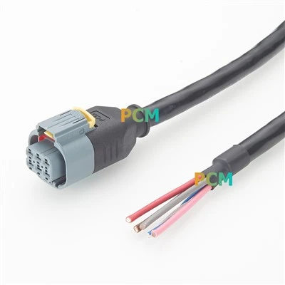
| Industrial camera data cable | - USB3.0 cable (with lock) - GigE (RJ45 Cat6 or Cat6a) - CoaXPress, CameraLink dedicated cable |
| Camera power cable | Some cameras require 6-pin Hirose or Molex power supply interface |
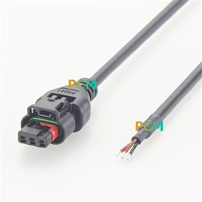
| Light source power cable | 24V power cable, mostly aviation head or M8 interface |
| Trigger signal cable | M8/M12 connector, connected to the trigger control signal of the camera or light source |
| Encoder/feedback cable | Encoder signal transmission, M12 A-coded common |
| Motor cable and driver cable | Shielded cable is usually used between the servo motor and the driver |
| Control communication cable | RS232/RS485, CAN, EtherCAT, Ethernet, Profinet, etc. |
| Display/USB interface cable | HDMI, DisplayPort, USB2.0/3.0 extension cable, used for external screen or mouse |
| Grounding and shielding cable | Anti-interference is very important, especially in high-speed motion and laser processing scenarios |