In the fields of industrial automation, machine vision and medical imaging, frame grabbers are an important bridge for transmitting image signals captured by industrial cameras to computers. Many users will notice a phenomenon when purchasing or installing: frame grabbers of different brands and interfaces have various connectors, some use BNC, some use DIN, some use USB, RJ45, and even multi-pin MDR or SDR interfaces. Why is this?
In fact, the diversity of connectors is not the "arbitrary design" of manufacturers, but is determined by multiple factors such as image transmission standards, signal requirements, speed bandwidth and application environment.
1. Connectors vary depending on image transmission standards
The transmission standard of industrial cameras determines the type of connector. Different standards use different physical interfaces. For example:
Camera Link: mostly used for high frame rate industrial cameras, usually using MDR 26-pin or SDR 26-pin connectors, supporting parallel data transmission, high speed but thicker cables.
- CoaXPress (CXP): uses DIN 1.0/2.3 or BNC connectors, and achieves up to 12.5 Gbps through coaxial cable, which is suitable for long-distance high-speed transmission.
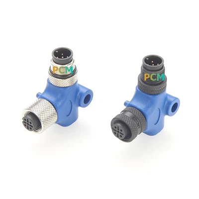
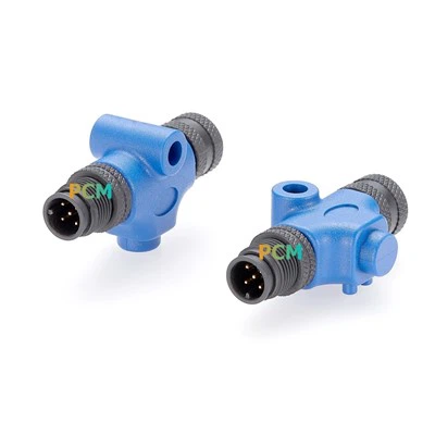
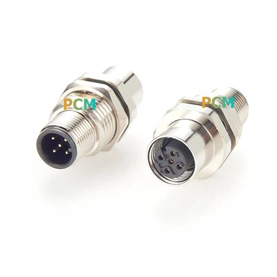
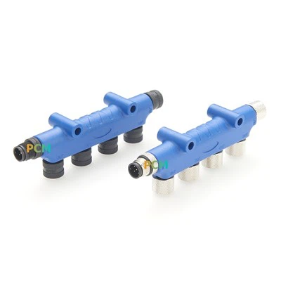
- GigE Vision: Based on Ethernet, the most common ones are RJ45 or the more compact ix Industrial / M12 X-coded connectors, which are suitable for long-distance network wiring.
- USB3 Vision: Commonly used USB 3.0 Micro-B, USB-C and other interfaces, with strong compatibility and plug-and-play support.
- SDI: Common in the broadcast and security industries, using BNC connectors, supporting hot plugging and high-definition signal transmission.

2. Different signal requirements correspond to different interface structures
Image acquisition cards not only need to transmit video data, but may also include trigger signals (Trigger), GPIO control, power supply and other functions. Therefore, some connectors will adopt a multi-pin-in-one design with a more complex structure. For example, the MDR interface on some Camera Link acquisition cards includes synchronization clocks and control signals in addition to image data.
3. High-speed transmission places higher demands on connector quality
With the improvement of image resolution and frame rate, data transmission rate is getting higher and higher. For example, CoaXPress 2.0 supports 12.5Gbps per channel, and USB3 Vision supports 5Gbps. These high-speed standards require connectors to have better impedance control and anti-interference capabilities. Therefore, industrial-grade connectors with locking design and good shielding structure are often used on acquisition cards to ensure stable and reliable transmission.

4. The application environment determines the physical form of the connector
In industrial sites, equipment often faces harsh environments such as vibration, dust, and high temperature. Therefore, many image acquisition cards use connectors with locking structures (such as Hirose, M12, DIN 1.0/2.3) to prevent signal interruption due to vibration. At the same time, in order to save space, some acquisition cards also use high-density and miniaturized connectors.
Summary
Behind the diverse image acquisition card connectors are the high requirements of industrial applications for performance, stability and compatibility. It is not only related to the transmission efficiency of video data, but also to the reliability of the entire machine vision system. Understanding the types and uses of these connectors will help us select the right connectors, arrange the wiring properly, and improve the overall efficiency and stability of the system.