

Product Specifications
| Parameter | Specification |
| Characteristic impedance | 90Ω |
| Cable outer diameter | 4.6mm |
| Frequency specified in drawing | 480MHz |
| Controlled cable length | 2000±20mm |
| PCM drawing number | PCM-ZC-0239 |
| Axial pull strength | 110N minimum |
| Insulation resistance | 100MΩ minimum |
| Operating temperature per drawing | −40°C to 105°C |
| Dielectric withstand voltage | 500V RMS minimum |
| Mating durability | 25 cycles minimum |
| Connector reference dimension | 31.25±0.15mm at each end |
| Connector configuration | Hirose GT17HN A Key at both ends |
| Contact layout | Four contacts in two rows at each end |
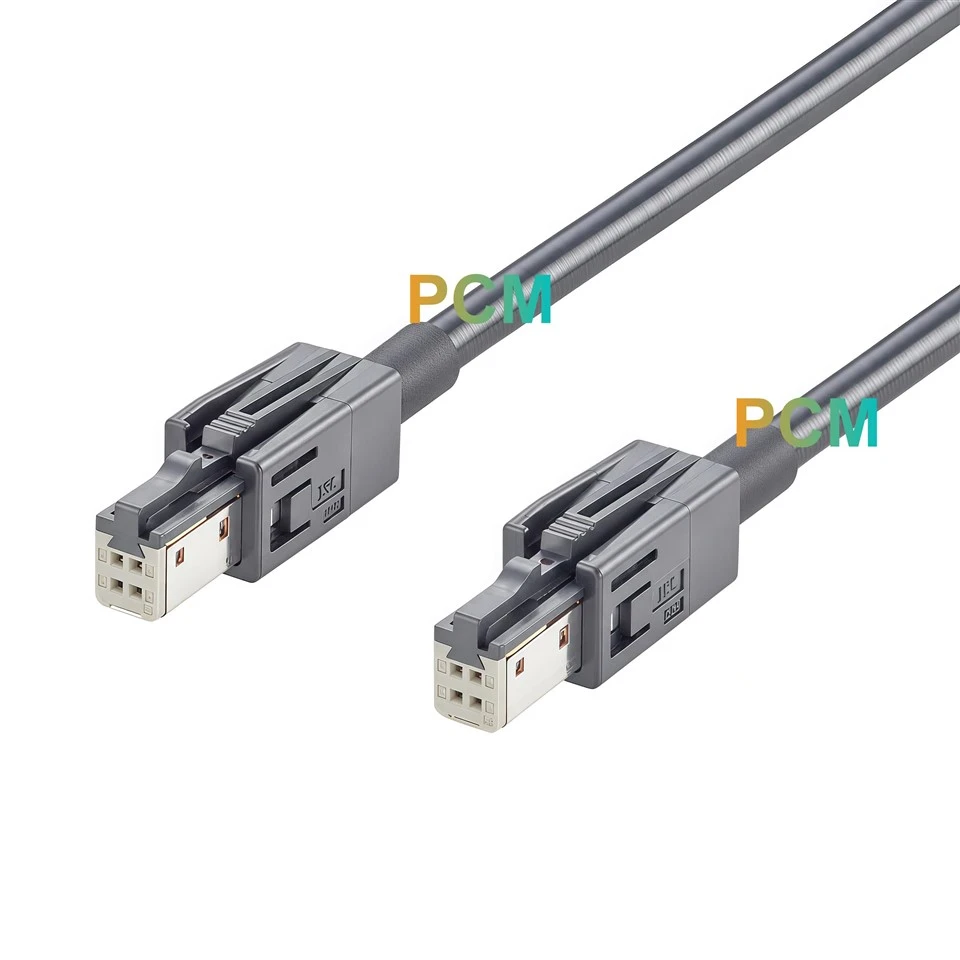
| Shell at each end | GT17HNS-4DS-HU, dark gray outer housing |
| Sleeve at each cable exit | Black, 5.0mm outer diameter and 20mm long |
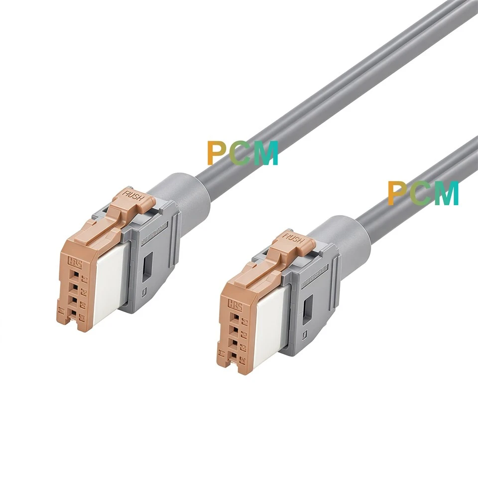
| Connector at each end | GT17HN-4DS-2C(A), brown A Key insulation case |
| Cable construction | Shielded USB 2.0 cable with one 26AWG pair and two 24AWG conductors |
How the Cable Fits Between Two Modules

Check Both Mating Faces
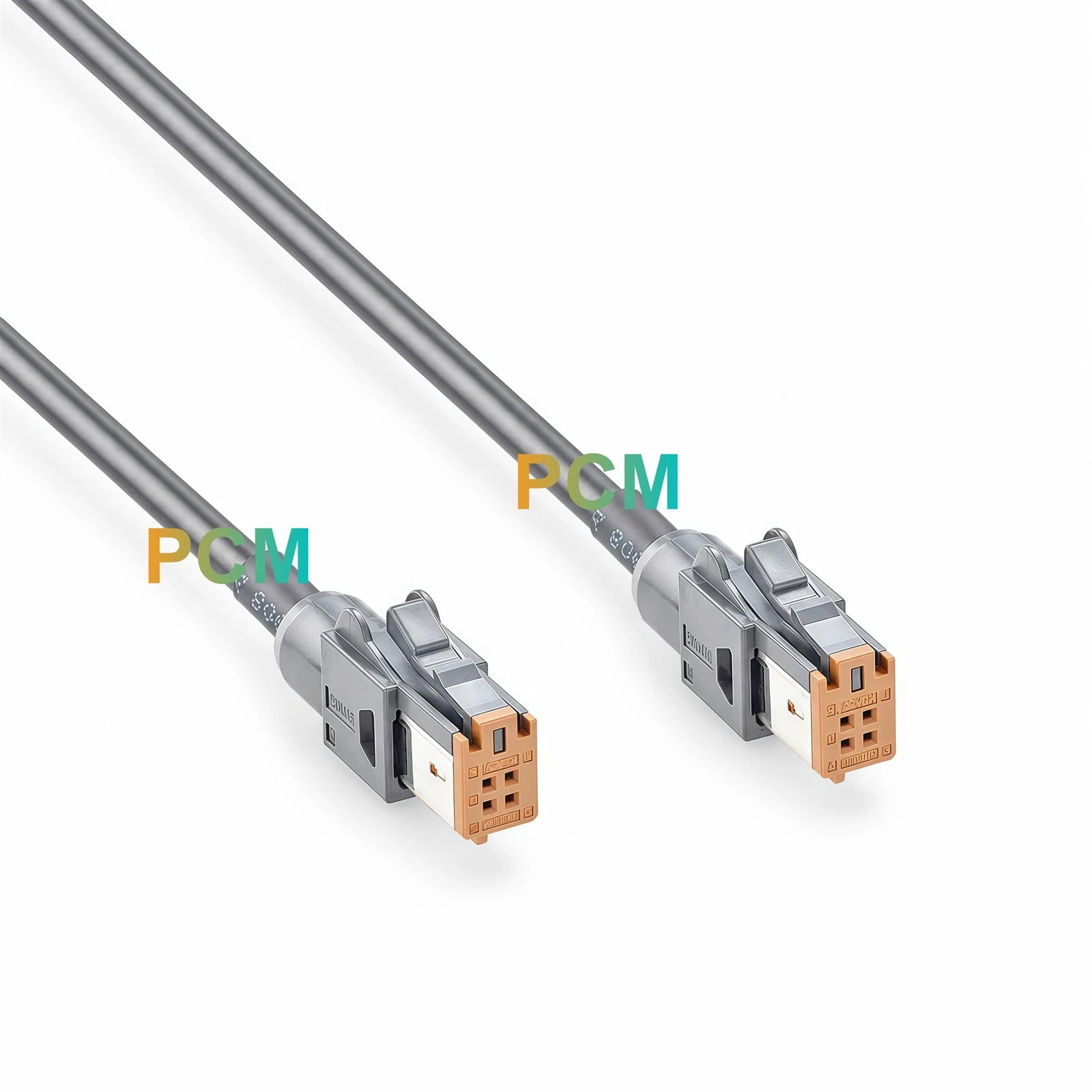
The brown face has two contacts above two more. That is the first detail to look for when a parts bin also contains single row GT17H leads. Check the port at each module, since two parts described as four position Hirose connectors may have different contact layouts or keys. The GT17HN-4DS-2C(A) connector is the brown insulation case that sets the A Key profile. The GT17HNS-4DS-HU shell is the dark gray housing around it. Include both numbers on the order to identify the complete end configuration.
Match the Signal Assignments Before Connecting
A signal on pin 2 at one end reaches pin 2 at the other end. The same rule applies to the other three contacts. When a test bench combines modules from different revisions, check that each signal reaches the position expected by the second module. The face views in the drawing show the connector from the mating side, which matters when an equipment schematic shows the rear. Use the molded contact numbers to orient each end before comparing the pinouts.

Check the Shield Separately From the Four Contacts
The 90Ω cable uses one 26AWG pair and two 24AWG conductors. The drawing identifies the four contact paths by wire color and shows a separate connection between the metal shells. A continuity fixture can check each numbered path and then check the shells as a separate step. For an automotive USB link, take the data, power and ground assignments from the module drawings. The cable drawing establishes where each conductor goes.
Leave Room to Unplug Either Module
The cable may reach both ports while leaving one latch too close to a bracket or trim panel. Check access above each release tab with the surrounding hardware installed. The 20mm sleeve at each cable exit also needs room before the route turns toward the first clip. Use the controlled cable span to check reach and the separate connector reference dimensions to check clearance. If a module slides out for service, check the route in both its installed and service positions.

Automotive Infotainment Applications
Vehicle console layout trials
Route the cable through a prototype console to check whether both ports remain accessible after the trim and brackets are fitted.
Module integration benches
Place the two modules at their intended spacing and check communication with the same connector key and wiring planned for the vehicle.
Head unit to media module integration
Connect a head unit and a remote USB media module when both have mating GT17HN A Key ports and compatible USB signal assignments.
Product Drawing

Product FAQ
Can either end connect to either module ?
Yes. Both ends have the same Hirose GT17HN A Key configuration and straight through wiring. Check that both ports mate with the cable and that their signal assignments match.
Will this cable fit a single row GT17H port ?
Choose a cable with the single row GT17H interface for that port. PCM-ZC-0239 uses four contacts in two rows at both ends.
Which part number identifies the A Key profile ?
GT17HN-4DS-2C(A) identifies the brown A Key insulation case. GT17HNS-4DS-HU identifies the dark gray outer housing.
Where is the cable length measured ?
The controlled dimension is 2000±20mm between the reference points shown on the drawing. Use the separate connector dimensions when checking the space needed for the complete assembly.
What should I include in a sample request ?
Send PCM drawing number PCM-ZC-0239 and your estimated quantity. If you need a different configuration, include the mating part number at each module, the required pin map and the target cable length.

Hot Tags: hirose gt17hn dual row a key to a key cable, China hirose gt17hn dual row a key to a key cable manufacturers, suppliers, factory