Steps to Replace a CAN Bus Cable Connector
As a supplier of CAN bus cable connectors, I've witnessed firsthand the importance of proper connector replacement in ensuring the smooth operation of CAN bus systems. In this blog post, I'll walk you through the steps to replace a CAN bus cable connector, from preparation to testing, to help you tackle this task with confidence.
Step 1: Gather the Necessary Tools and Materials
Before you begin the replacement process, it's essential to gather all the tools and materials you'll need. Here's a list of items you should have on hand:
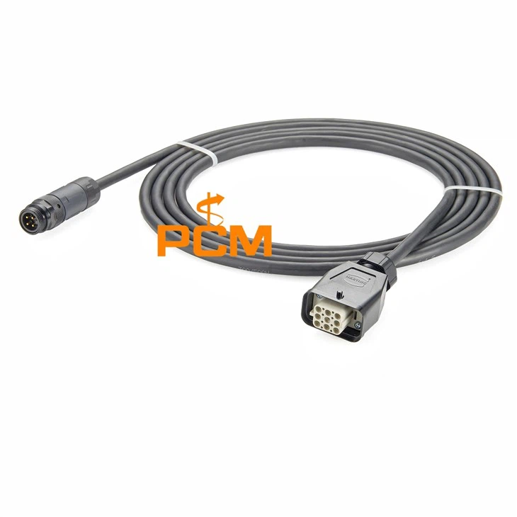
- Replacement Connector: Choose a connector that is compatible with your CAN bus system. For example, you might consider the CANopen Connector RS232 with Programming Port, CAN-Bus Connector D-Sub 9 Pin To M12, or Field Bus CAN Bus D-Sub To M12.
- Wire Strippers: These are used to remove the insulation from the cable wires.
- Crimping Tool: A crimping tool is necessary to attach the connector to the cable.
- Soldering Iron and Solder (Optional): In some cases, soldering may be required for a more secure connection.
- Heat Shrink Tubing: This provides insulation and protection for the connection.
- Multimeter: A multimeter is used to test the continuity and voltage of the CAN bus system.
Step 2: Disconnect the Power
Safety should always be your top priority when working with electrical systems. Before you start replacing the connector, make sure to disconnect the power supply to the CAN bus system. This will prevent any electrical shocks or damage to the equipment.
Step 3: Remove the Old Connector
Once the power is disconnected, carefully remove the old connector from the cable. This may involve unscrewing or unclipping the connector, depending on its type. Take note of the wire connections and the orientation of the connector to ensure proper installation of the new one.
Step 4: Prepare the Cable
After removing the old connector, you'll need to prepare the cable for the new connector. Use the wire strippers to remove about 1/4 to 1/2 inch of insulation from the end of each wire. Be careful not to damage the wires while stripping the insulation.
Step 5: Attach the New Connector
Now it's time to attach the new connector to the cable. If the connector uses crimp terminals, insert the stripped wires into the appropriate terminals and use the crimping tool to secure them. Make sure the crimp is tight and the wires are firmly held in place.
If the connector requires soldering, apply a small amount of solder to the terminals and then carefully solder the wires to the terminals. Use a soldering iron with a fine tip to avoid overheating the wires or the connector.


Step 6: Insulate the Connection
Once the connector is attached, use heat shrink tubing to insulate the connection. Slide the heat shrink tubing over the connection and use a heat gun or a lighter to shrink the tubing. The tubing should fit tightly around the connection, providing insulation and protection.
Step 7: Reconnect the Power
After the connection is insulated, reconnect the power supply to the CAN bus system. Make sure all the connections are secure and there are no loose wires.
Step 8: Test the Connection
Once the power is reconnected, use a multimeter to test the continuity and voltage of the CAN bus system. Check the resistance between the CAN high and CAN low wires to ensure there is no short circuit. Also, measure the voltage across the CAN bus to make sure it is within the acceptable range.
If the test results are satisfactory, the connector replacement was successful. If there are any issues, double-check the connections and repeat the testing process.
Step 9: Secure the Connector
Finally, secure the connector in place to prevent it from moving or coming loose. This may involve using cable ties or mounting brackets to hold the connector in position.
Conclusion
Replacing a CAN bus cable connector may seem like a daunting task, but by following these steps, you can do it safely and effectively. Remember to always use the right tools and materials, and take your time to ensure a proper connection.
If you have any questions or need further assistance with CAN bus cable connectors, feel free to reach out to us. We're here to help you find the right solutions for your CAN bus system. Whether you're looking for a specific connector or need advice on installation, our team of experts is ready to assist you. Contact us today to discuss your requirements and start a fruitful procurement process.
References
- CAN in Automation (CiA). "CANopen Communication Profile Specification."
- ISO 11898-1:2015, "Road vehicles -- Controller area network (CAN) -- Part 1: Data link layer and physical signalling."