

一, Current thermal effect: energy conversion trap under high current
The heating essence of M8 adapter is Joule heating generated when current passes through a conductor, and its heat formula is:
Q = I² × R × t
Among them, Q is heat, I is current, R is conductor resistance, and t is electrification time. When the current exceeds the rated value of the adapter, the heat increases in the square order, causing a sharp rise in internal temperature. For example, test data from a certain industrial robot manufacturer shows that when the working current of the M8 adapter increases from 2A to 4A, its internal temperature skyrockets from 50 ℃ to 85 ℃ within 10 minutes, far exceeding the safety threshold.
1. Amplification effect of contact resistance
The contacts of the M8 adapter (such as pins and sockets) have a small contact resistance, and high current will exacerbate local heating. Taking the M8-HT series of a German connector manufacturer as an example, its contact resistance design value is ≤ 5m Ω, but under 4A current, the power loss of a single contact point reaches 0.08W (P=I ² R). If there is oxidation or contamination on the contact surface, the resistance may increase to 20m Ω, and the power loss may soar to 0.32W, causing the contact point temperature to exceed 120 ℃, leading to deformation or even melting of the plastic insulator.
2. Thermal stability challenges of conductor materials
The internal wires of M8 adapters are usually made of tin plated copper or gold-plated copper, and their temperature resistance level is limited. For example, the long-term operating temperature of ordinary PVC insulated wires is only 70 ℃, and the heat generated by high current may cause local temperatures to exceed this limit, leading to aging and brittleness of the insulation layer. The case of a certain automotive electronics manufacturer shows that the insulation layer of the M8 adapter, which has been overloaded for a long time, cracked within 6 months, ultimately causing a short circuit fault.
二, Thermal Design: Technological Evolution from Passive Conduction to Active Cooling
To address the issue of high current heating, the heat dissipation design of M8 adapters needs to balance structural optimization and material innovation. The following are the mainstream solutions in the industry:
1. Optimization of heat conduction path
Metal heat dissipation shell: It adopts aluminum alloy or copper alloy shell, and conducts internal heat to the surface of the shell through thermal conductive silicone grease. The M8 adapter from a certain manufacturer uses a 6061 aluminum alloy shell, combined with a 0.5mm thick thermal pad, to reduce the thermal resistance from 2.5 ℃/W to 0.8 ℃/W.
Embedded heat pipe: Integrating micro heat pipes inside the adapter to quickly transfer heat using phase change principles. Tests conducted by a medical equipment manufacturer have shown that heat pipe technology can reduce the temperature rise of adapters by 40% under high current conditions.
2. Enhanced convective heat dissipation
Fin type heat dissipation structure: improves natural convection efficiency by increasing the surface area of the shell. The M8 adapter from a certain industrial robot manufacturer uses 12 0.5mm thick fins. Under 2A current, the heat dissipation area increases from 50cm ² to 150cm ², and the temperature rise is controlled within 15 ℃.
Forced air cooling system: For extreme high current scenarios (such as>5A), some manufacturers integrate micro fans inside the adapter. A solution from a semiconductor equipment manufacturer shows that air cooling technology can enable the adapter to operate stably at 8A current, with a temperature rise not exceeding 25 ℃.
3. Application of Phase Change Materials (PCM)
Fill the adapter with paraffin based or salt phase change materials and achieve temperature buffering by melting and absorbing heat. Tests conducted by a certain aerospace manufacturer have shown that PCM technology can reduce the peak temperature of the M8 adapter by 30 ℃ under short-term overload (such as 10A/30 seconds), providing critical time for system protection.
三, Industry Practice: From Standard Setting to Scenario Adaptation
1. International standards and certification requirements
The IEC 61076-2-104 standard specifies that M8 adapters must pass a "current overload test": operate continuously for 1 hour at 150% rated current, with a temperature rise not exceeding 40 ℃. For example, a UL certified M8 adapter with a rated current of 3A showed a temperature rise of only 32 ℃ during a 4.5A overload test, far below the standard limit.
2. Scenario based solutions
Industrial robot joints: In response to high-frequency insertion and vibration environments, a certain manufacturer has launched a "separate heat dissipation design", which separates the contact module from the heat dissipation shell and achieves efficient heat conduction through liquid metal thermal paste. After 20000 insertions and removals, the contact resistance fluctuates by less than 2m Ω and the temperature rise stabilizes within 10 ℃.
New energy vehicle charging system: In order to meet the demand for high current charging, a certain car company adopts the "dual M8 adapter parallel connection" scheme, where the current of a single adapter is reduced to 2.5A. Combined with a water-cooled cooling system, the temperature rise of the charging module is controlled within 5 ℃, and the service life is extended to 10 years.
四, Solution: Full cycle management from prevention to maintenance
1. Optimization during the design phase
Current margin design: Select adapter specifications based on 120% -150% of the rated current. For example, if the maximum current of the device is 4A, a 6A rated adapter should be selected to reduce the risk of long-term high load.
Simulation verification: Use software such as ANSYS to perform thermal mechanical coupling simulation, optimize contact layout and heat dissipation path. The simulation results of a certain manufacturer show that by adjusting the pin spacing from 2mm to 3mm, the local hotspot temperature can be reduced by 15 ℃.
2. Monitoring during the usage phase
Temperature sensor integration: An NTC thermistor is embedded inside the adapter to monitor temperature in real-time and provide feedback to the control system through an I ² C interface. The practice of a logistics AGV manufacturer has shown that this solution can reduce the overheating failure rate by 80%.
Intelligent current limiting: dynamically adjust the output current through MCU to avoid overload operation. For example, a power management chip can automatically reduce the current from 5A to 3A when it detects that the adapter temperature is greater than 60 ℃.
3. Maintenance phase management
Regular cleaning: Use compressed air to remove dust from the heat dissipation holes and prevent an increase in thermal resistance. According to statistics from an electronics manufacturer, cleaning and maintenance can extend the lifespan of adapters by 30%.
Contact maintenance: After every 5000 insertions and removals, clean the contact surface with isopropanol and apply conductive grease to reduce contact resistance. A certain test shows that this measure can reduce the temperature rise at the contact point by 10 ℃.
M8 Sensor Actuator Splitter And Cable Overview
Popular Products

HFM Mini FAKRA Cable
Single channel HFM Mini-FAKRA coaxial cable with female-female, male-male and male-female options for ADAS cameras and

IP67 Waterproof HFM FAKRA Cable
IP67 waterproof HFM to FAKRA cable with 4 connector configurations for automotive cameras, ADAS sensors and RF systems.

Hirose ST Series Connector
Hirose ST Series connector cable assemblies featuring ST40X-10S-CV, ST40X-18S-CV, ST40X-24S-CV and ST40X-36S-CV

GMSL2 FAKRA Z Code Camera Cable
3 m GMSL2 cable with FAKRA Z Code female connectors for camera-to-host, ECU, ADAS and machine vision connections.
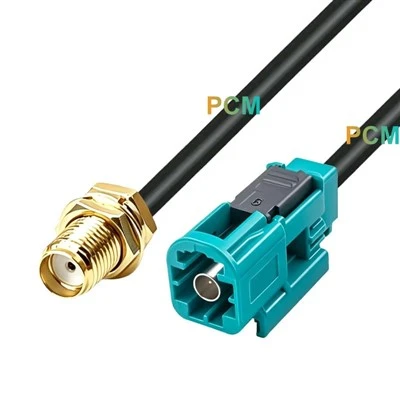
Rosenberger Fakra To SMA Cable
Rosenberger to SMA 50 Ohm coaxial cable with four connector configurations for automotive RF modules, antennas and test
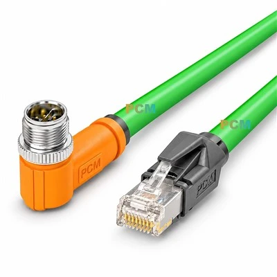
M12 X-Code To RJ45 Cable
M12 X-Code to RJ45 Cat6A cable for 10Gb industrial Ethernet, compatible with X-coded M12 devices, switches and