01
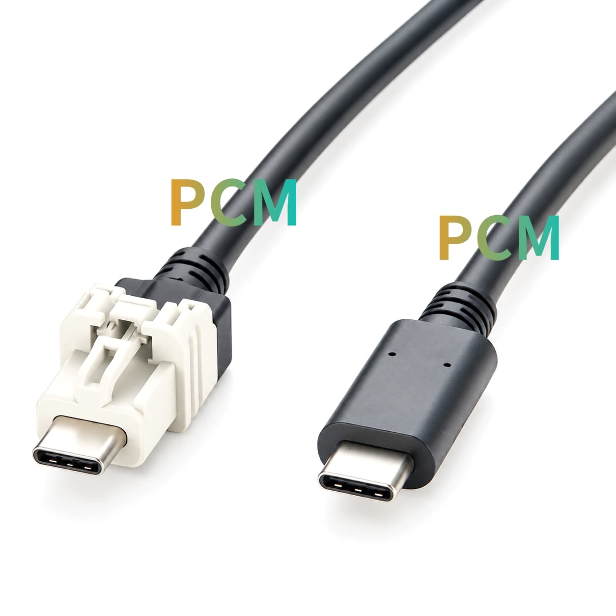
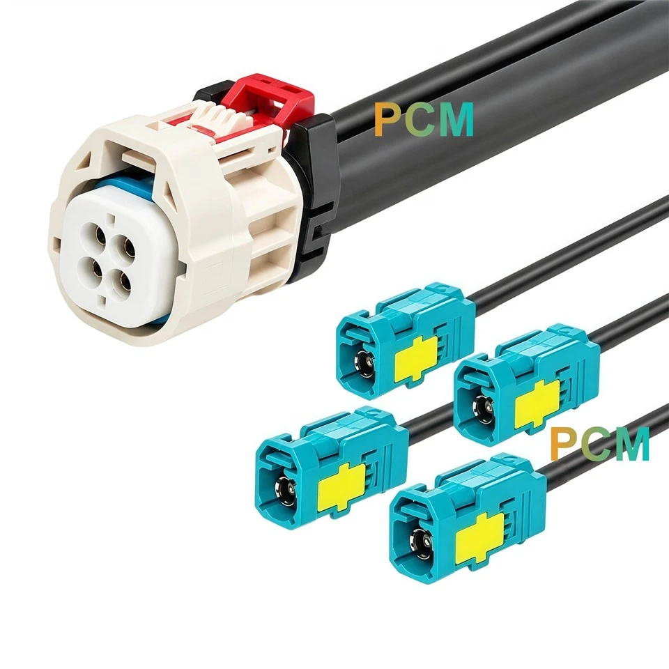
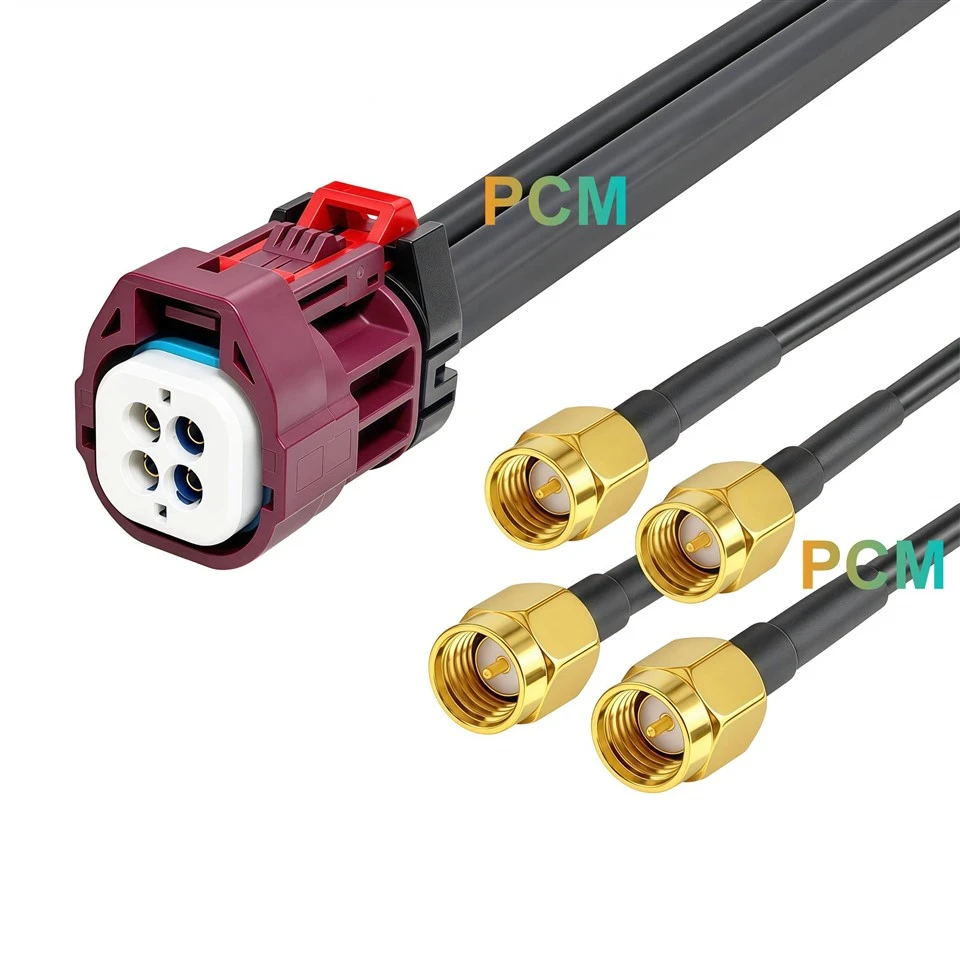
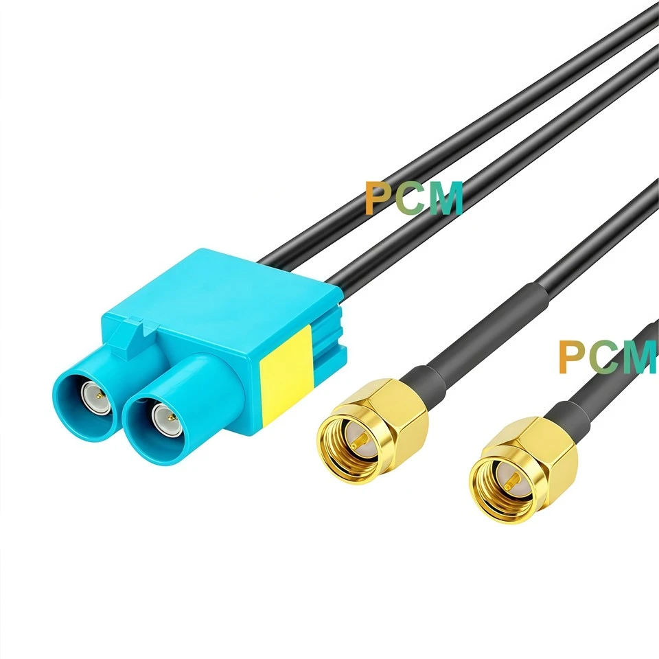
In-stock Product Display
|
|
|
|
What Is the 2398010-1 Product ?
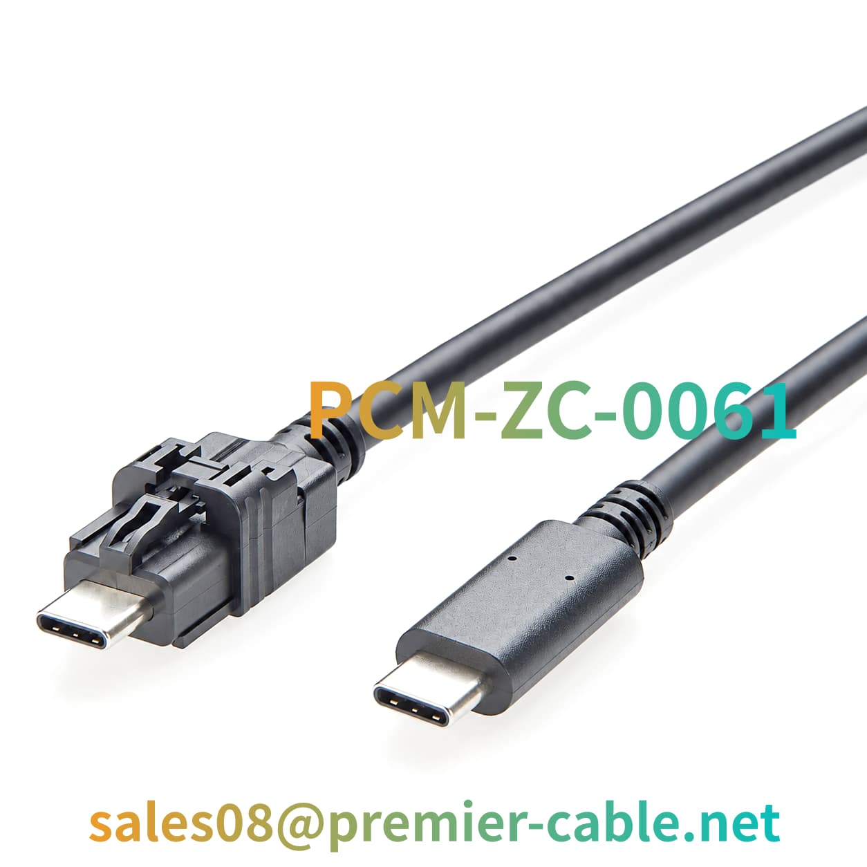
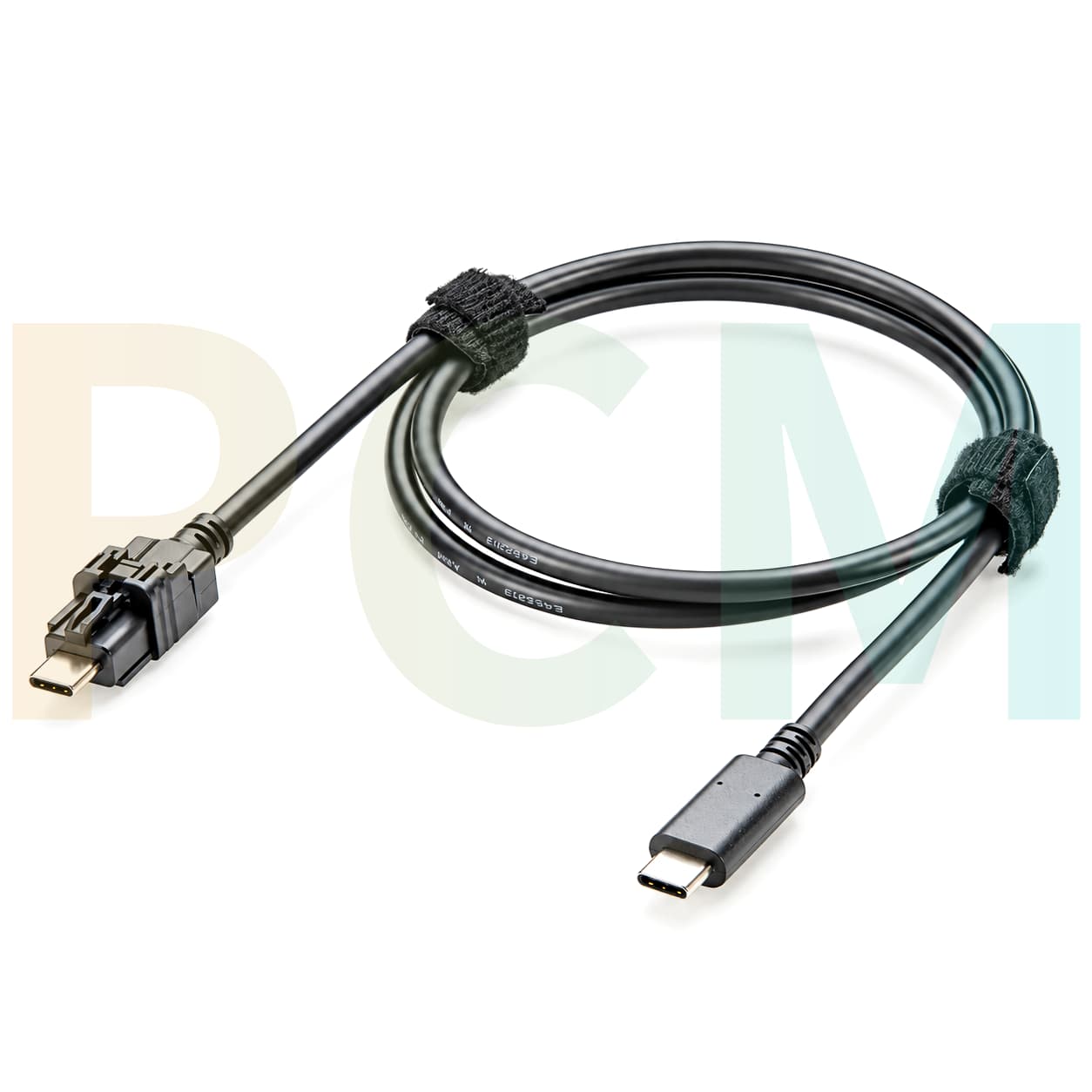
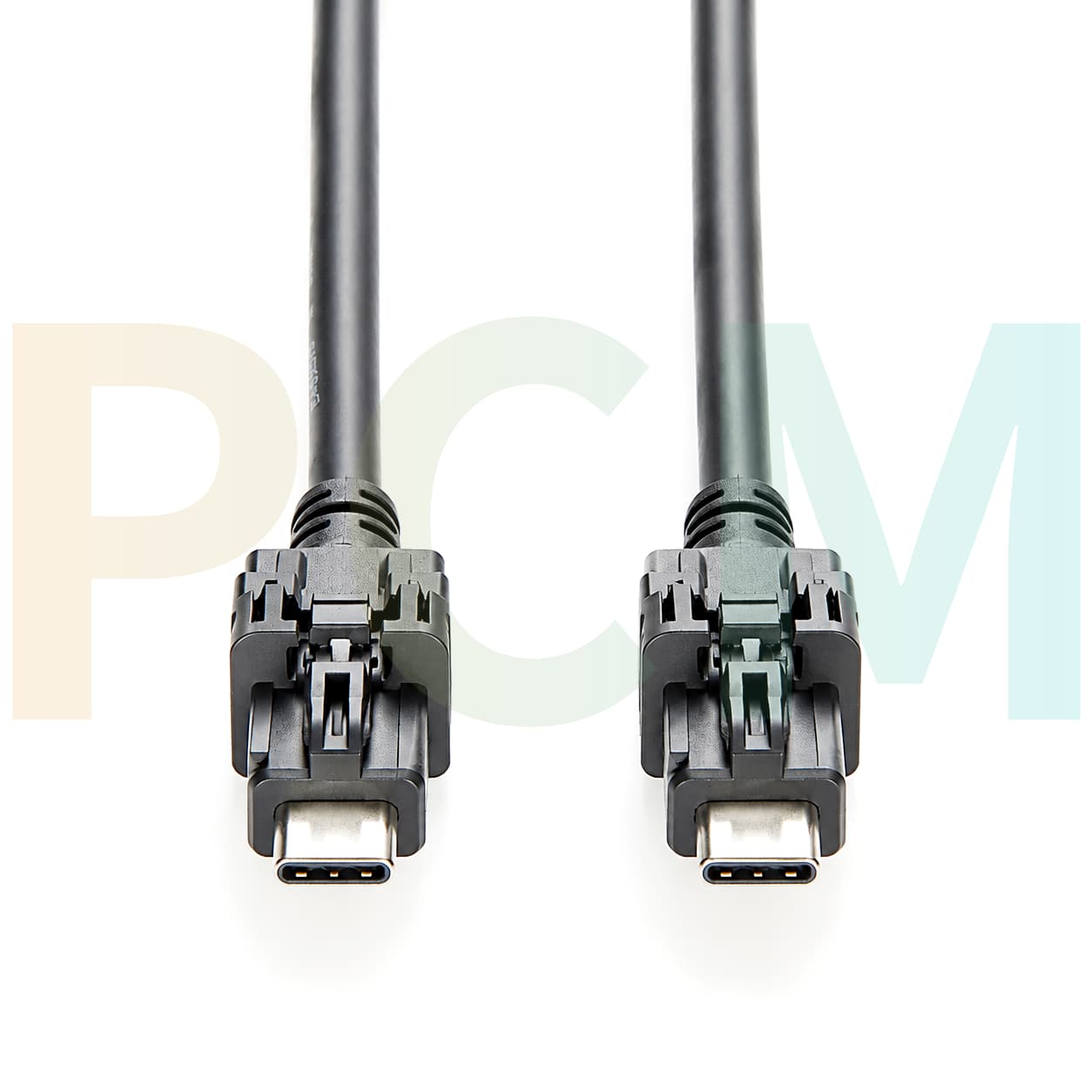
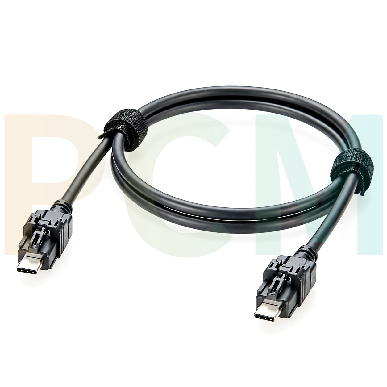
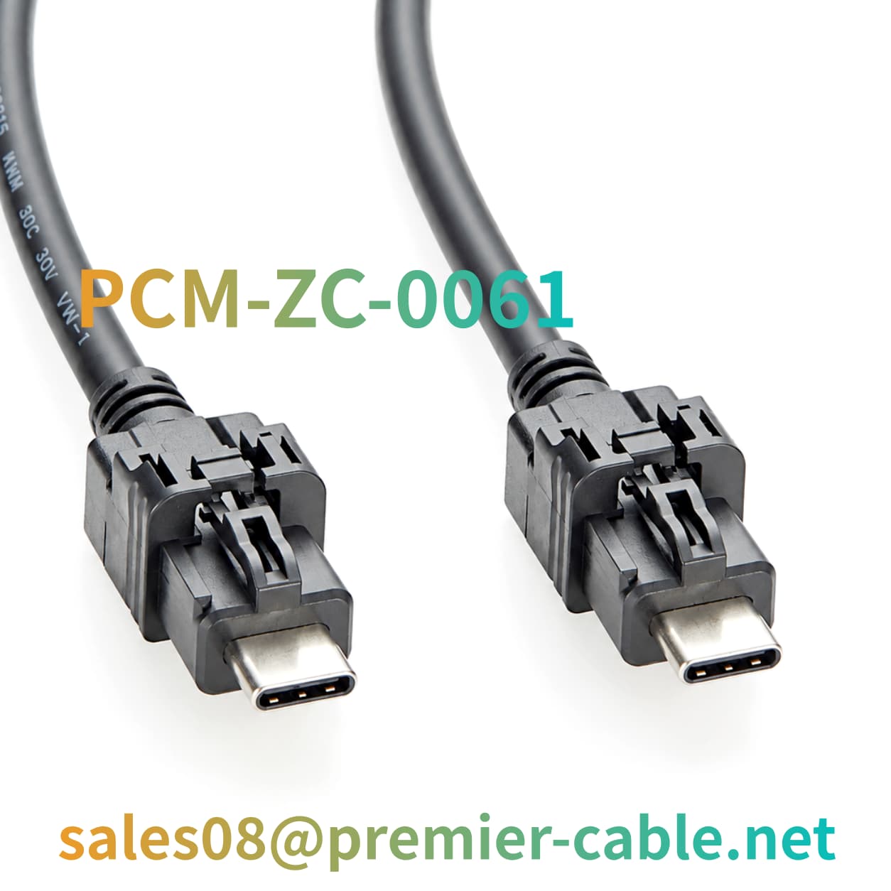
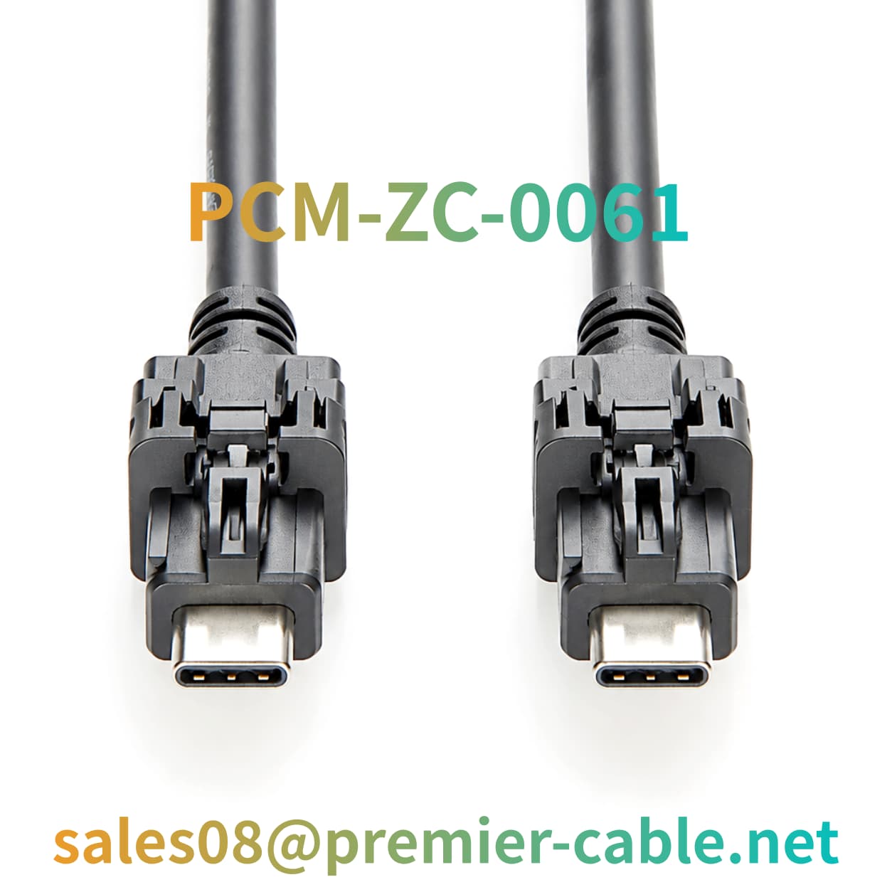
The TE Connectivity 2398010-1 is a vertical male USB Type-C connector assembly featuring A Code coding. Official product information classifies it as a USB 3.1 Gen 1 connector with 22 positions, a single port, and a cable-mount configuration. Its primary function is to provide a connection interface in systems that meet the relevant mechanical and electrical requirements.
When combined with a suitable cable, termination components, and a connector at the opposite end, this connector can form part of a USB Type-C cable assembly for wired connections between automotive electronic devices. Whether the finished cable supports specific data-transfer, power-delivery, or other functions depends on the complete assembly design, wiring assignments, connected equipment, and applicable USB specifications.
What Does This Product Do ?
- Provides a Defined Connection Interface
The 2398010-1 provides a USB Type-C male interface, helping engineers verify dimensions, connection orientation, and mating requirements while reducing configuration errors.
-
Supports Wired Connectivity in Automotive Electronics
- Facilitates Harness Integration and Volume Assembly
Defining the connector part number, termination method, and cable requirements helps standardize bills of materials, assembly procedures, and inspection criteria, improving efficiency in OEM customization, wholesale purchasing, and volume production.
Why Use This Product ?
◆ Resolves Unclear Interface Configuration
Automotive electronics projects may involve equipment from different generations, different interface layouts, and multiple suppliers. Purchasing a cable solely under the generic name "USB-C" can overlook differences in connector coding, mounting orientation, contact configuration, or termination structure. Using the specific 2398010-1 part number as a design input provides a concrete starting point for technical verification, although compatibility with the complete cable and target equipment must still be confirmed.
◆ Reduces Uncertainty in Harness Design and Production
In volume assembly, inconsistent cable lengths, incorrect terminations, unsuitable connector orientation, or shielding that does not meet design requirements can lead to rework and quality issues. By defining connector, cable, and inspection requirements before production, project teams can identify potential problems earlier and incorporate critical requirements into sample approval and outgoing inspection procedures.
Product Pain Point Analysis
Similar Appearance Does Not Ensure Mechanical Compatibility
USB Type-C is a common interface format, but assemblies may differ in internal construction, termination, mounting, and application requirements. Similar appearance does not guarantee interchangeability. Check official drawings, part-number suffixes, and the equipment's mating interface before selection.
Connector Specifications Do Not Define Complete Cable Performance
The USB version is only one evaluation factor. Overall cable performance also depends on conductor design, impedance control, shielding, cable length, and termination quality. For specific data rates or power requirements, validate the complete cable assembly rather than relying solely on connector specifications.
Automotive Applications Require Installation and Durability Evaluation
Automotive electronics may experience temperature changes, vibration, limited space, and repeated cable bending. Connector specifications alone cannot confirm that the complete cable meets automotive environmental requirements. Evaluate strain relief, bend radius, retention, operating temperature, and necessary environmental tests based on the installation location.
How to Select the Right Product ?
Step 1: Confirm the Equipment Interface and Connector Coding
First, confirm the actual interface type, connector construction, and A Code configuration required by the equipment. Do not make purchasing decisions solely from a product name or appearance image. Compare the target interface with the manufacturer's drawings and confirm connection orientation, installation clearance, and mating-connector compatibility.
Step 2: Define Both Ends of the Finished Cable
Determine whether the product is a single-ended USB Type-C connector assembly or a fully assembled cable with connectors at both ends. If the opposite end must connect to USB Type-C, USB-A, a dedicated automotive connector, or another interface, specify its model, gender, pin assignments, and mechanical requirements. This prevents a single connector assembly from being mistakenly purchased as a complete cable.
Step 3: Confirm Data and Power Requirements
Identify the required data types, target transfer rate, and whether power delivery is needed for the intended equipment. Then verify that conductor count, pair construction, shielding, impedance, termination, and testing meet the design requirements. If USB Power Delivery or a specific power level is required, confirm the relevant electrical design and verification evidence separately.
Step 4: Confirm the Installation Environment and Cable Construction
For automotive electronics applications, confirm cable length, outside diameter, bend radius, retention method, strain relief, temperature range, and expected vibration conditions. If the connection location presents moisture or other environmental risks, verify that the complete assembly has the required protective design. The official 2398010-1 specification identifies it as non-sealable, so it should not be described as a waterproof connector without supporting verification.
Product FAQ
How Do USB Type-C Form Factors Differ from USB Transfer Performance ?
USB Type-C primarily describes the connector interface format, whereas USB transfer performance also depends on the applicable USB specification, internal cable construction, termination quality, and device capabilities. USB Type-C cables with the same external appearance may differ in supported data rates, power-delivery capabilities, and specific functions.
For a finished cable using TE Connectivity 2398010-1, the correct approach is to confirm the connector configuration first and then verify the technical specifications and test results of the complete cable. This prevents the connector's USB version from being treated as a guarantee of finished-cable performance in every application.
What Is A Code, and Why Is Coding Verification Important ?
A Code is configuration-identification information included in the product description for this model. In automotive connector projects, verifying the code helps identify the specific product version and guides engineers in checking the corresponding drawings, mating interfaces, and assembly requirements.
Selection should not rely on the A Code designation alone to establish compatibility, nor should direct interchangeability with other coded versions be assumed without formal technical evidence. The correct process is to verify the complete part number, manufacturer drawings, and mating connector before carrying out any necessary mechanical and electrical validation.
Why Do Automotive Cables Require Attention to Shielding and Signal Integrity ?
Automotive electronic equipment may contain switching power supplies, motor drives, wireless communication modules, and other electronic circuits, each presenting different electromagnetic compatibility requirements. For high-speed USB data connections, conductor layout, differential-pair construction, impedance control, shielding design, and termination quality can all affect signal integrity.
However, the fact that a connector is intended for automotive electronics does not automatically mean that every cable using it meets specific electromagnetic compatibility requirements. Engineering teams should define the shielding approach according to the target equipment design and validate the complete assembly through applicable testing.
Can Customized USB Type-C Cables Be Supplied ?
Customization requirements can be evaluated. Depending on the project, cable length, connector combinations, jacket color, termination method, identification, and packaging may be discussed. Actual feasibility depends on connector supply conditions, technical specifications, and sample validation results. Before volume production, the approved product drawings and inspection standards should be confirmed by both parties.